
The Battery Clinic - 2009/01
Correct Deans Ultra connector soldering technique
Red Scholefield | [email protected]
Although both the Deans Ultra and Anderson Powerpole are excellent connectors, some people shy away from the Deans because of the perceived difficulty in soldering. They can be tricky for the novice, and you can easily destroy the connector if you are not careful. I prefer the Deans Ultra because it is a bit more compact than the Powerpole.
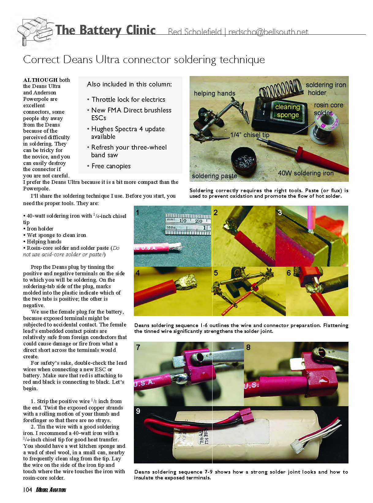
Before you start, you need the proper tools:
- 40-watt soldering iron with 1/4-inch chisel tip
- Iron holder
- Wet sponge to clean iron
- Helping hands (alligator clips)
- Rosin-core solder and solder paste (do not use acid-core solder or paste!)
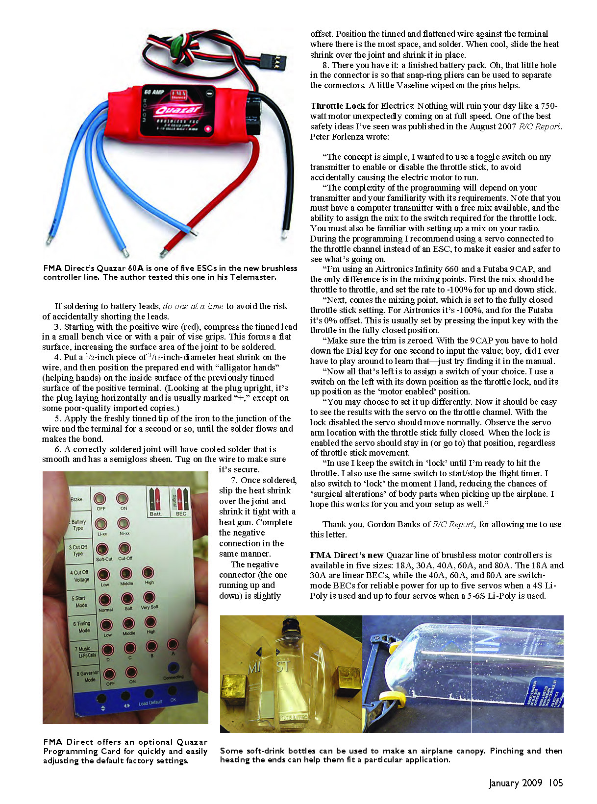
Prep the Deans plug by tinning the positive and negative terminals on the side to which you will be soldering. On the soldering-tab side of the plug, marks molded into the plastic indicate which tab is positive; the other is negative.
We use the female plug for the battery because exposed terminals might be subjected to accidental contact. The female lead's embedded contact points are relatively safe from foreign conductors that could cause damage or fire from a direct short across the terminals.
For safety's sake, double-check the lead wires when connecting a new ESC or battery. Make sure that red attaches to red and black connects to black. Let's begin.
- Strip the positive wire 1/8 inch from the end. Twist the exposed copper strands with a rolling motion of your thumb and forefinger so there are no stray strands.
- Tin the wire with a good soldering iron. I recommend a 40-watt iron with a 1/4-inch chisel tip for good heat transfer. Keep a wet kitchen sponge and a wad of steel wool in a small can nearby to frequently clean slag from the tip. Lay the wire on the side of the iron tip and touch the junction of wire and iron with rosin-core solder so the wire takes solder evenly.
If soldering to battery leads, do one at a time to avoid the risk of accidentally shorting the leads.
- Starting with the positive wire (red), compress the tinned lead in a small bench vice or with a pair of vise grips. This forms a flat surface, increasing the surface area of the joint to be soldered.
- Put a 1/2-inch piece of 3/16-inch-diameter heat shrink on the wire, and then position the prepared end with helping hands on the inside surface of the previously tinned surface of the positive terminal. (Looking at the plug upright, it's the plug laying horizontally and is usually marked "+," except on some poor-quality imported copies.)
- Apply the freshly tinned tip of the iron to the junction of the wire and the terminal for a second or so, until the solder flows and makes the bond.
- A correctly soldered joint will have cooled solder that is smooth and has a semi-gloss sheen. Tug on the wire to make sure it's secure.
- Once soldered, slip the heat shrink over the joint and shrink it tight with a heat gun. Complete the negative connection in the same manner. The negative connector (the one running up and down) is slightly offset. Position the tinned and flattened wire against the terminal where there is the most space, and solder. When cool, slide the heat shrink over the joint and shrink it in place.
- There you have it: a finished battery pack. The little hole in the connector is so snap-ring pliers can be used to separate the connectors. A little Vaseline wiped on the pins helps.
Also included in this column
- Throttle lock for electrics
- New FMA Direct brushless ESCs
- Hughes Spectra 4 update available
- Refresh your three-wheel band saw
- Free canopies
Throttle Lock for Electrics
Nothing will ruin your day like a 750-watt motor unexpectedly coming on at full speed. One of the best safety ideas I’ve seen was published in the August 2007 R/C Report. Peter Forlenza wrote:
“The concept is simple: I wanted to use a toggle switch on my transmitter to enable or disable the throttle stick, to avoid accidentally causing the electric motor to run.
“The complexity of the programming will depend on your transmitter and your familiarity with its requirements. Note that you must have a computer transmitter with a free mix available, and the ability to assign the mix to the switch required for the throttle lock. You must also be familiar with setting up a mix on your radio. During the programming I recommend using a servo connected to the throttle channel instead of an ESC, to make it easier and safer to see what’s going on.
“I’m using an Airtronics Infinity 660 and a Futaba 9CAP; the only difference is in the mixing points. First the mix should be throttle to throttle, and set the rate to -100% for up and down stick.
“Next comes the mixing point, which is set to the fully closed throttle stick setting. For Airtronics it’s -100%, and for the Futaba it’s 0% offset. This is usually set by pressing the input key with the throttle in the fully closed position.
“Make sure the trim is zeroed. With the 9CAP you have to hold down the Dial key for one second to input the value; boy, did I ever have to play around to learn that—just try finding it in the manual.
“Now all that’s left is to assign a switch of your choice. I use a switch on the left with its down position as the throttle lock, and its up position as the ‘motor enabled’ position.
“You may choose to set it up differently. Now it should be easy to see the results with the servo on the throttle channel. With the lock disabled the servo should move normally. Observe the servo arm location with the throttle stick fully closed. When the lock is enabled the servo should stay in (or go to) that position, regardless of throttle stick movement.
“In use I keep the switch in ‘lock’ until I’m ready to hit the throttle. I also use the same switch to start/stop the flight timer. I also switch to ‘lock’ the moment I land, reducing the chances of ‘surgical alterations’ of body parts when picking up the airplane. I hope this works for you and your setup as well.”
Thank you to Gordon Banks of R/C Report for allowing use of this letter.
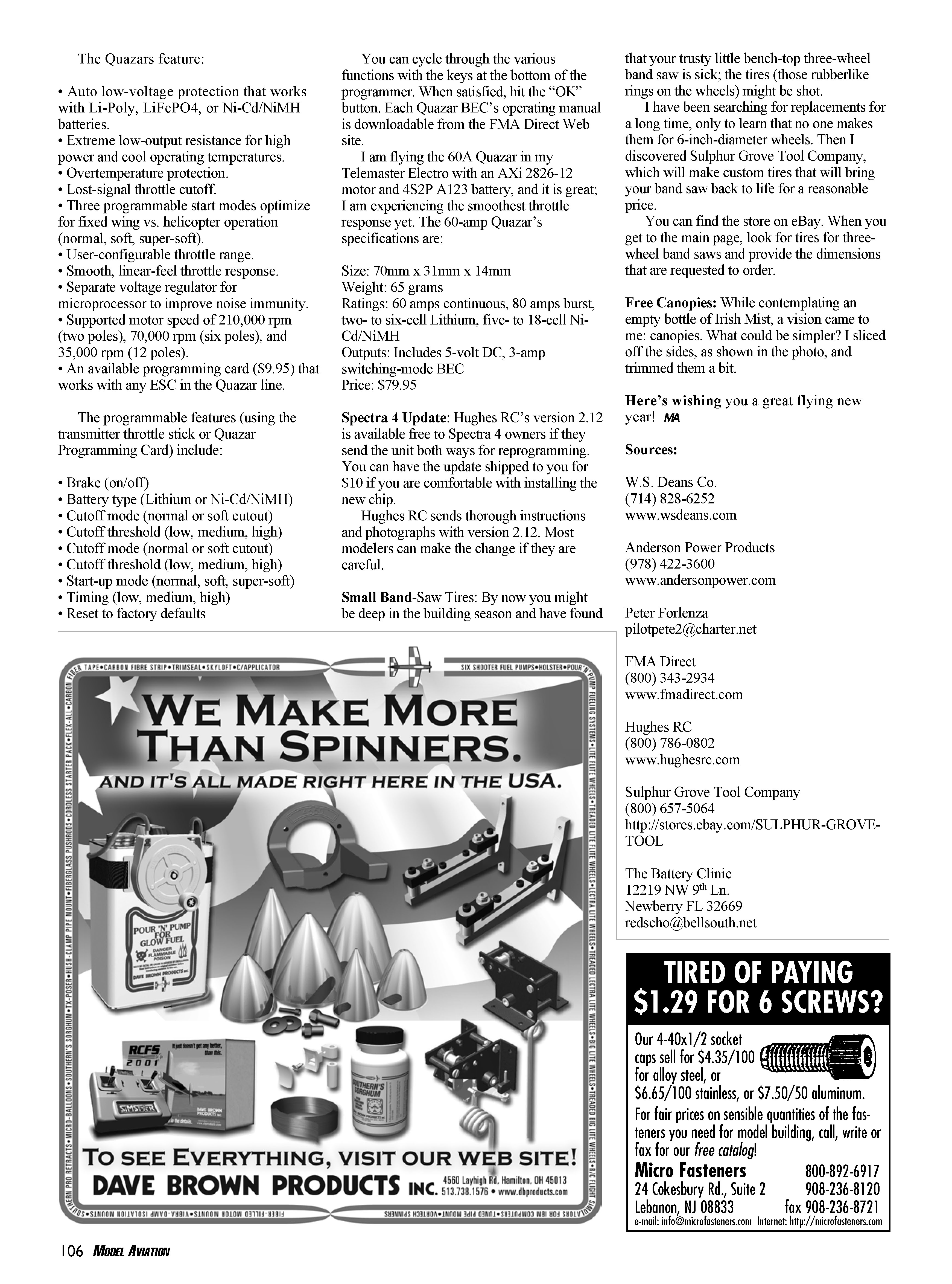
FMA Direct Quazar brushless ESCs
FMA Direct’s new Quazar line of brushless motor controllers is available in five sizes: 18A, 30A, 40A, 60A, and 80A. The 18A and 30A are linear BECs, while the 40A, 60A, and 80A are switch-mode BECs for reliable power for up to five servos when a 4S Li-Poly is used and up to four servos when a 5–6S Li-Poly is used.
The Quazars feature:
- Auto low-voltage protection that works with Li-Poly, LiFePO4, or Ni-Cd/NiMH batteries
- Extremely low output resistance for high power and cool operating temperatures
- Overtemperature protection
- Lost-signal throttle cutoff
- Three programmable start modes optimized for fixed wing vs. helicopter operation (normal, soft, super-soft)
- User-configurable throttle range
- Smooth, linear-feel throttle response
- Separate voltage regulator for microprocessor to improve noise immunity
- Supported motor speeds: 210,000 rpm (two poles), 70,000 rpm (six poles), and 35,000 rpm (12 poles)
- An available programming card ($9.95) that works with any ESC in the Quazar line
Programmable features (using the transmitter throttle stick or Quazar Programming Card) include:
- Brake (on/off)
- Battery type (Lithium or Ni-Cd/NiMH)
- Cutoff mode (normal or soft cutout)
- Cutoff threshold (low, medium, high)
- Start-up mode (normal, soft, super-soft)
- Timing (low, medium, high)
- Reset to factory defaults
You can cycle through the various functions with the keys at the bottom of the programmer. When satisfied, hit the "OK" button. Each Quazar BEC's operating manual is downloadable from the FMA Direct Web site.
I am flying the 60A Quazar in my Telemaster Electro with an AXi 2826-12 motor and a 4S2P A123 battery, and it is great; I am experiencing the smoothest throttle response yet.
60A Quazar specifications:
- Size: 70 mm x 31 mm x 14 mm
- Weight: 65 grams
- Ratings: 60 amps continuous, 80 amps burst; two- to six-cell Lithium, five- to 18-cell Ni-Cd/NiMH
- Outputs: Includes 5-volt DC, 3-amp switching-mode BEC
- Price: $79.95
Hughes Spectra 4 update
Hughes RC's Spectra 4 version 2.12 is available free to Spectra 4 owners if they send the unit both ways for reprogramming. You can have the update shipped to you for $10 if you are comfortable with installing the new chip.
Hughes RC sends thorough instructions and photographs with version 2.12. Most modelers can make the change if they are careful.
Small band-saw tires
By now you might be deep in the building season and have found that your trusty little bench-top three-wheel band saw is sick; the tires (those rubber-like rings on the wheels) might be shot.
I have been searching for replacements for a long time, only to learn that no one makes them for 6-inch-diameter wheels. Then I discovered Sulphur Grove Tool Company, which will make custom tires that will bring your band saw back to life for a reasonable price.
You can find the store on eBay. When you get to the main page, look for tires for three-wheel band saws and provide the dimensions that are requested to order.
Free canopies
While contemplating an empty bottle of Irish Mist, a vision came to me: canopies. What could be simpler? I sliced off the sides of the bottle and trimmed them a bit to form canopies.
Here's wishing you a great flying new year! — MA
Sources
W.S. Deans Co. (714) 828-6252 www.wsdeans.com
Anderson Power Products (978) 422-3600 www.andersonpower.com
Peter Forlenza [email protected]
FMA Direct (800) 343-2934 www.fmadirect.com
Hughes RC (800) 786-0802 www.hughesrc.com
Sulphur Grove Tool Company (800) 657-5064 http://stores.ebay.com/SULPHUR-GROVE-TOOL
The Battery Clinic 12219 NW 9th Ln. Newberry, FL 32669 [email protected]
Transcribed from original scans by AI. Minor OCR errors may remain.

