

The Battery Clinic 2010/07
"C": What is it all about?
Even after several years of use in our hobby, there still seems to be confusion about the “C rate” for Li-Poly batteries. Until Li-Poly technology entered the modeling scene, “C” stood for capacity of the battery. It was a measure of how much energy could be drawn out in a given time period.
Theoretically, a 1 amp-hour battery would deliver 1 amp for 1 hour. I write “theoretically” because manufacturers actually rate them at the five-hour (C/5) discharge rate. This was felt to be the typical application discharge.
All was well until power tools and other energy hogs came into being. By that time the rating method was well entrenched, so there was no reason to change it.
The “C rate” of a Li-Poly battery is a whole other beast that Li-Poly vendors (not cell manufacturers) created to indicate the maximum discharge the pack could tolerate without significant damage. It became a “mine is better than yours” thing that entertains marketing types who find real numbers depressing. Deciding what “significant damage” was was left to the user, I guess, because the vendors have been a bit remiss in defining it. One said it was the maximum rate the pack could be discharged at and not exceed 140º, which theoretically was the temperature at which bad things began to happen.
The definition of “bad” is basically left up to the user. I do know, and many have learned the hard (expensive) way, that the harder you drive Li-Polys, the sooner they are ready for the graveyard.
We see packs rated at 10C, 15C, 20C, 30C, and even some as high as 50C. This implies that you can discharge the pack at whatever the C is multiplied by the actual capacity. A 40C 2000 mAh pack could be discharged at 80 amps. At that rate a 2000 mAh (2.0 Ah) pack would last about 1.5 minutes (approximately 90 seconds).
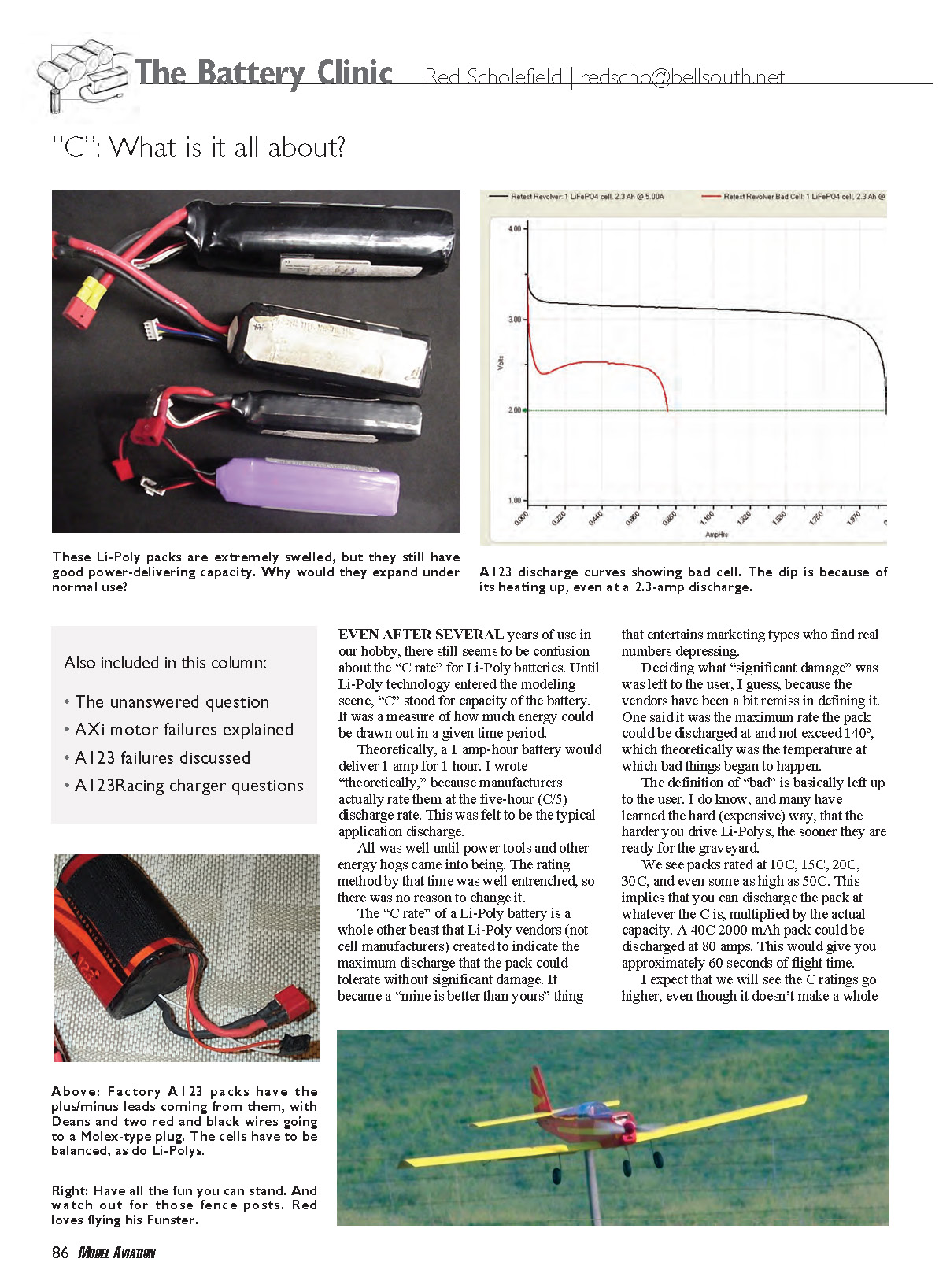
I expect that we will see C ratings go higher, even though it doesn't make a whole lot of sense. Swelling of packs under load and during storage is a continuing concern. Decomposition of solvents used in the manufacturing process is also suspect. If anyone has had better luck than I have trying to get an explanation of swelling under normal use — what the mechanism is — I hope you will share that information so I can report it here.
AXi Motor Failure Explained
L.A. Johnson, a technician who worked for Hobby Lobby before retirement, offers the following explanation of the AXi motor failure that I covered in the March column. He wrote:
"I need to tell you why you had the problem with the AXi 2820/14 motor, and how to cure the problem.
"The motor is a very early model. I can tell because the magnets are not keyed into the rotating end bell, and because the rotating end bell will not accept the prop adapter that is used when the motor is reverse-mounted.
"First, let’s cover the field coils rotating on the motor core.
"The field coils are machine-wound, and then they are 'glued' to the motor core using an epoxy adhesive. The problem with doing it that way is if the adhesive gets too hot, you don’t get a complete glue line between the two; the field coils can break loose and rotate on the core under hard acceleration or 'braking' action.
"The cure for this is similar to what you do when you are trying to glue a dowel into a hole: cut a spiral groove around the dowel so the glue spreads over the whole length of the dowel.
"All the later-model AXi motors have a spiral groove around the core so the glue spreads over the whole length of the core/field-coil joint. In addition, the manufacturer went to a higher-temperature adhesive, which also helped.
"Now, on to the magnets. AXi found that the adhesive they were using on these early motors was defective, and it did not have enough shear strength to hold the magnets in place during heavy acceleration and deceleration. They changed to a higher..."
[Text ends here — OCR source cut off.]
Transcribed from original scans by AI. Minor OCR errors may remain.

