
BEECHCRAFT D-17-S
Clarence Haught
Introduction
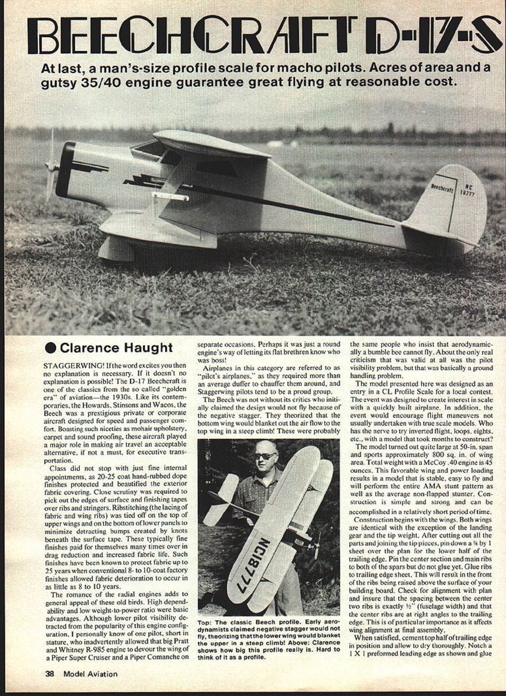
STAGGERWING! If the word excites you then no explanation is necessary. If it doesn't, no explanation is possible! The D-17 Beechcraft is one of the classics from the so-called "golden era" of aviation—the 1930s. Like its contemporaries, the Howards, Stinsons and Wacos, the Beech was a prestigious private or corporate aircraft designed for speed and passenger comfort. Boasting such niceties as mohair upholstery, carpet and soundproofing, these aircraft played a major role in making air travel an acceptable alternative, if not a must, for executive transportation.
Class did not stop with just fine internal appointments. Twenty to twenty-five coat hand-rubbed dope finishes protected and beautified the exterior fabric covering. Close scrutiny was required to pick out the edges of surface and finishing tapes over ribs and stringers. Rib-stitching (the lacing of fabric and wing ribs) was tied off on the top of upper wings and on the bottom of lower panels to minimize detracting bumps created by knots beneath the surface tape. These typically fine finishes paid for themselves many times over in drag reduction and increased fabric life. Such finishes have been known to protect fabric up to 25 years when conventional 8- to 10-coat factory finishes allowed fabric deterioration to occur in as little as 8 to 10 years.
The romance of radial engines adds to the general appeal of these old birds. High dependability and low weight-to-power ratio were basic advantages. Although lower pilot visibility detracted from the popularity of this engine configuration, I personally know one pilot, short in stature, who inadvertently allowed that big Pratt & Whitney R-985 engine to devour the wing of a Piper Super Cruiser and a Piper Comanche on separate occasions. Perhaps it was just a round engine's way of letting its flat brethren know who was boss!
Airplanes in this category are referred to as "pilot's airplanes," as they required more than an average duffer to chauffeur them around, and Staggerwing pilots tend to be a proud group.
The Beech was not without its critics who initially claimed the design would not fly because of the negative stagger. They theorized that the bottom wing would blanket out the airflow to the top wing in a steep climb. About the only real criticism that was valid at all was the pilot visibility problem, but that was basically a ground handling problem.
Model purpose and summary
The model presented here was designed as an entry in a CL Profile Scale for a local contest. The event was designed to create interest in scale with a quickly built airplane and to encourage flight maneuvers not usually undertaken with true scale models. Who has the nerve to try inverted flight, loops, eights, etc., with a model that took months to construct?
The model turned out quite large at 50" span and sports approximately 800 sq. in. of wing area. Total weight with a McCoy .40 engine is 45 oz. This favorable wing and power loading results in a model that is stable, easy to fly and will perform the entire AMA stunt pattern as well as the average non-flapped stunter. Construction is simple and strong and can be accomplished in a relatively short period of time.
Construction overview
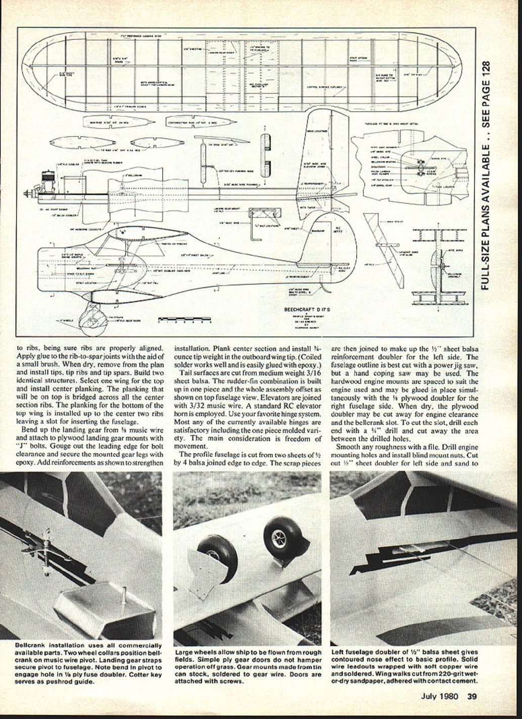
Construction begins with the wings. Both wings are identical with the exception of the landing gear and the tip weight. After cutting out all the parts and joining the tip pieces:
- Pin a 3/8" x 1" sheet over the plan for the lower half of the trailing edge.
- Pin the center main ribs to the two spars but do not glue yet.
- Glue ribs to the trailing edge sheet. This will result in the front of the ribs being raised above the surface of your building board.
- Check for alignment with the plan and ensure the spacing between the center two ribs is exactly 1/2" (fuselage width) and that the center ribs are at right angles to the trailing edge. This is particularly important as it affects wing alignment at final assembly.
- When satisfied, cement the top half of the trailing edge in position and allow to dry thoroughly.
- Notch a 1" x 1" preformed leading edge as shown and glue in position; allow to dry thoroughly.
- Apply glue to rib-to-spar joints and, with a small brush, remove excess.
- Install tip ribs and tip spars. Build two identical structures.
Select the wing top and install center planking. Planking will be bridged across center section ribs. Plank the bottom top wing installed up to the center two ribs leaving a slot for inserting the fuselage. Bend up landing gear C-wire and attach plywood landing gear mounts and J-bolts. Gouge out the leading edge for bolt clearance to secure mounted gear legs and epoxy. Add reinforcements shown to strengthen installation. Plank the center section and install 1 oz tip weight on the outboard wingtip. Coiled solder works well and is easily glued with epoxy.
Tail surfaces
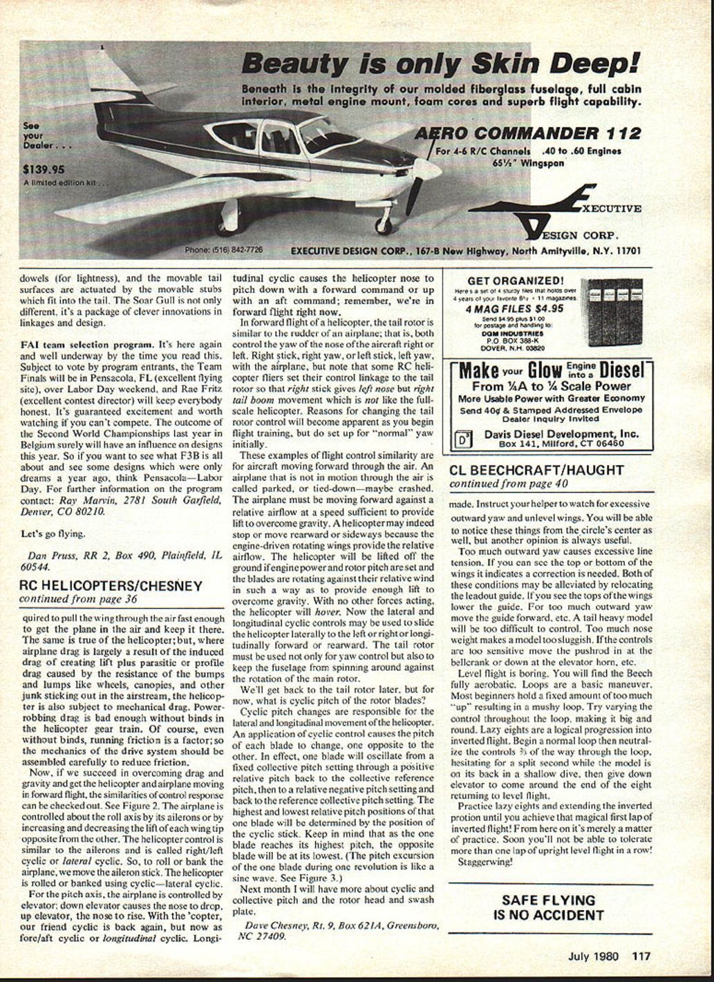
Tail surfaces are cut from medium-weight 3/16" sheet balsa. The rudder-fin combination is built up in one piece and the whole assembly is offset as shown on the top fuselage view. Elevators are joined with 3/32" music wire. A standard RC elevator horn is employed. Use your favorite hinge system; most currently available hinges are satisfactory, including the one-piece molded variety. The main consideration is freedom of movement.
Fuselage
The profile fuselage is cut from two sheets of 1/4" balsa joined edge to edge. The scrap pieces are then joined to make up the 1/2" sheet balsa reinforcement doubler for the left side. The fuselage outline is best cut with a power jigsaw, but a hand coping saw may be used. The hardwood engine mounts are spaced to suit the engine used and may be glued in place simultaneously with the 1/8" plywood doubler for the right fuselage side.
When dry, the plywood doubler may be cut away for engine clearance and the bellcrank slot. To cut the slot, drill each end with a 1/8" drill and cut away the area between the drilled holes. Smooth any roughness with a file. Drill engine mounting holes and install blind-mount nuts.
Cut out the 1/8" sheet doubler for the left side and sand to fit and shape before gluing to the fuselage side. Complete the bellcrank slot after the glue has dried. Complete sanding of the total fuselage. Note the taper at the rear to match the rudder offset. Check fit of fuselage-to-wing joints and adjust as required by trimming or adding small strips of balsa. This joint should fit well without causing any misalignment of the wings.
A little extra time fitting these joints will pay off in appearance and flight characteristics.
The plan shows two 1/4" reinforcing dowels to strengthen the profile fuselage in the wing mount area. These are purely optional. If you are using light wood or are anticipating an occasional rollover landing they are advisable. If you are using firm wood they are probably unnecessary.
Pre-finishing and covering
At this point some preliminary finishing steps are necessary. All components receive a final sanding and are given two coats of clear dope, lightly sanded between coats. Cover the sheet tail parts with GM Silkspan. This is best accomplished by laying the dry paper on the wood and brushing on a coat of dope thinned 1 part dope to 2 parts thinner. Covering these surfaces not only contributes greatly to their resistance to splitting and overall strength but makes filling the grain much easier. This procedure is also desirable on the fuselage, but is more difficult due to all the curves. Lightly dampening the Silkspan with a spray bottle will help in this respect and does not really affect the dope-thinner mixture all that much.
Wings should be covered with GM or SGM Silkspan applied damp. Lay a dry piece on the wing structure and position it as desired. Dampen with a spray bottle and smooth out any wrinkles. Carefully lift edges and apply dope to the perimeter of the structure. There is no need to apply dope to the ribs or center-section planking at this time as this will take place during subsequent coats. Cover tips separately from the main panels, using a smaller piece to aid in avoiding wrinkles. Trim off any excess tissue and build up a good clear dope finish consisting of 4 to 5 brushed coats. A very light wipe-down with 600-grit sandpaper between coats will yield a smooth finish. Just be careful not to sand through the paper on the high spots: ribs, etc.
Assembly
When satisfied with your base finish, assemble the complete model. Begin with the stabilizer-elevator. Be sure it is level (perpendicular to the fuselage side) and square with the fuselage center line. Glue securely and install the triangular reinforcements shown on the plan. It is wise to poke a series of small holes into the wood under the glue joints to allow good glue penetration for a secure bond. Install the rudder in the offset position as shown on the plan.
Attach wings with epoxy glue paying particular attention to their alignment as mentioned during the construction phase. Utilize your square and check wing tip-to-tail measurements with a tape measure.
When dry, trim tissue from between strut attachment ribs and install wing struts. If any warps are evident you may correct them by steaming prior to installing struts. Slight warps can be corrected when installing struts. Triangular pieces are then cut from 1/8" sheet balsa to produce a faired-in look to the struts.
You may wish to provide some fillets between the wing and fuselage joints and perhaps to smooth out any imperfections at the edges of the doublers. An excellent product for this is microballoons. Mix the microballoons in some 5-minute epoxy and apply to model. Form the fillets with a finger dipped in dope thinner. This technique allows molding and shaping of the fillets without sanding.
Landing gear and doors
The landing gear doors are cut from 1/16" plywood and are attached to the landing gear wire by means of a tin strap cut from a food can lid. The strap should be soldered to the 1/8" music wire. The gear doors are secured with small sheet-metal screws or with small nails cut to length and soldered in place. These doors are quite durable even if you fly from grass fields, and add to the appearance of the model.
Final finish and trim
The final finish is now applied. Brushed-on color finishes are acceptable, but for a neat job spraying is best. The original model was sprayed with orange Aero-Gloss dope and all trimming was done with Monokote trim sheet. Control surface outlines were formed from vinyl tape obtained from an automotive parts house. Wing walks were cut from 220-grit wet-or-dry sandpaper and secured with contact cement.
Control system
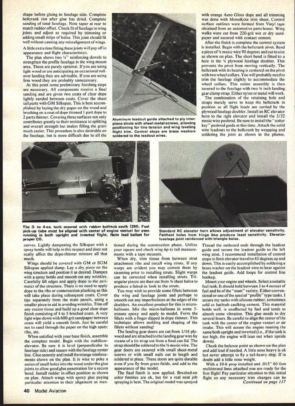
After the finish is complete, the control system is installed. Begin with the bellcrank pivot. Bend a piece of 5/64" music wire 90 degrees and cut to size as shown on the plan. The short bend is fitted to a hole in the 1/8" plywood fuselage doubler. This prevents the pivot from moving vertically. The bellcrank with its bearing is centered on the pivot with two wheel collars. You will probably need to trim the fuselage slightly to accommodate the wheel collars. This entire assembly is then secured to the fuselage with two 1/8" landing-gear clamp straps. Either nylon or metal will work.
The combination of the retaining hole and straps merely serves to keep the bellcrank in position as all flight loads are carried by the plywood fuselage doubler. Install an RC elevator horn to the right elevator and install the 3/32" music wire pushrod. Be sure to install the "cotter key" pushrod guide at this time. Attach the solid wire leadouts to the bellcrank by wrapping and soldering the joint as shown in the photos.
Thread the outboard ends through the leadout guide and secure the leadout guide to the left wing strut. Installation of control stops to limit elevator travel to 45° up and down is recommended. This is easily accomplished by soldering a brass washer on the leadout wire to bear against the leadout guide. Add loops for control-line hookup.
Engine, tank and balance
Mount your engine and wheels. Select a suitable fuel tank. It should hold between 3 to 4 ounces of fuel and be of the "stunt" variety. Either conventional or one of the special "profile" type tanks will do. I secure my tanks with silicone rubber, sometimes sold as bathtub caulking cement. This material holds well, is unaffected by fuel and tends to absorb some vibration. This glue needs to dry several hours. Be careful to align the center of the tank with the center of the engine venturi or air intake. This will assure the engine runs the same both upright and inverted (i.e., if the tank is too high, the engine will lean out when upside down).
Check the balance point as shown on the plan and add lead if needed. A little nose heavy is OK but never attempt to fly a tail-heavy ship. If in doubt, add a little nose weight.
With a 10" x 6" prop installed and .015"–.060" 60-foot multistrand lines attached you are ready for the first flights! Pay particular attention to this initial flight so any necessary trim changes can be made.
Trimming and flight advice
Instruct your helper to watch for excessive outward yaw and unlevel wings. You will be able to notice these things from the circle's center as well, but another opinion is always useful. Too much outward yaw causes excessive line tension. If you can see the top or bottom of the wings it indicates a correction is needed. Both of these conditions may be alleviated by relocating the leadout guide:
- If you see the tops of the wings, lower the guide.
- For too much outward yaw, move the guide forward.
A tail-heavy model will be too difficult to control. Too much nose weight makes a model too sluggish. If the controls are too sensitive, move the pushrod in at the bellcrank or down at the elevator horn.
Level flight is boring. You will find the Beech fully aerobatic. Loops are a basic maneuver. Most beginners hold a fixed amount of up resulting in a mushy loop. Try varying the control throughout the loop, making it big and round. Lazy eights are a logical progression into inverted flight. Begin a normal loop then neutralize the controls two-thirds of the way through the loop, hesitating for a split second while the model is on its back in a shallow dive, then give down elevator to come around the end of the eight returning to level flight.
Practice lazy eights and extend the inverted portion until you achieve that magical first lap of inverted flight! From here on it's merely a matter of practice. Soon you'll not be able to tolerate more than one lap of upright level flight in a row!
Staggerwing!
Transcribed from original scans by AI. Minor OCR errors may remain.

