

Beginner's Guide to FREE FLIGHT
by Don DeLoach [email protected]
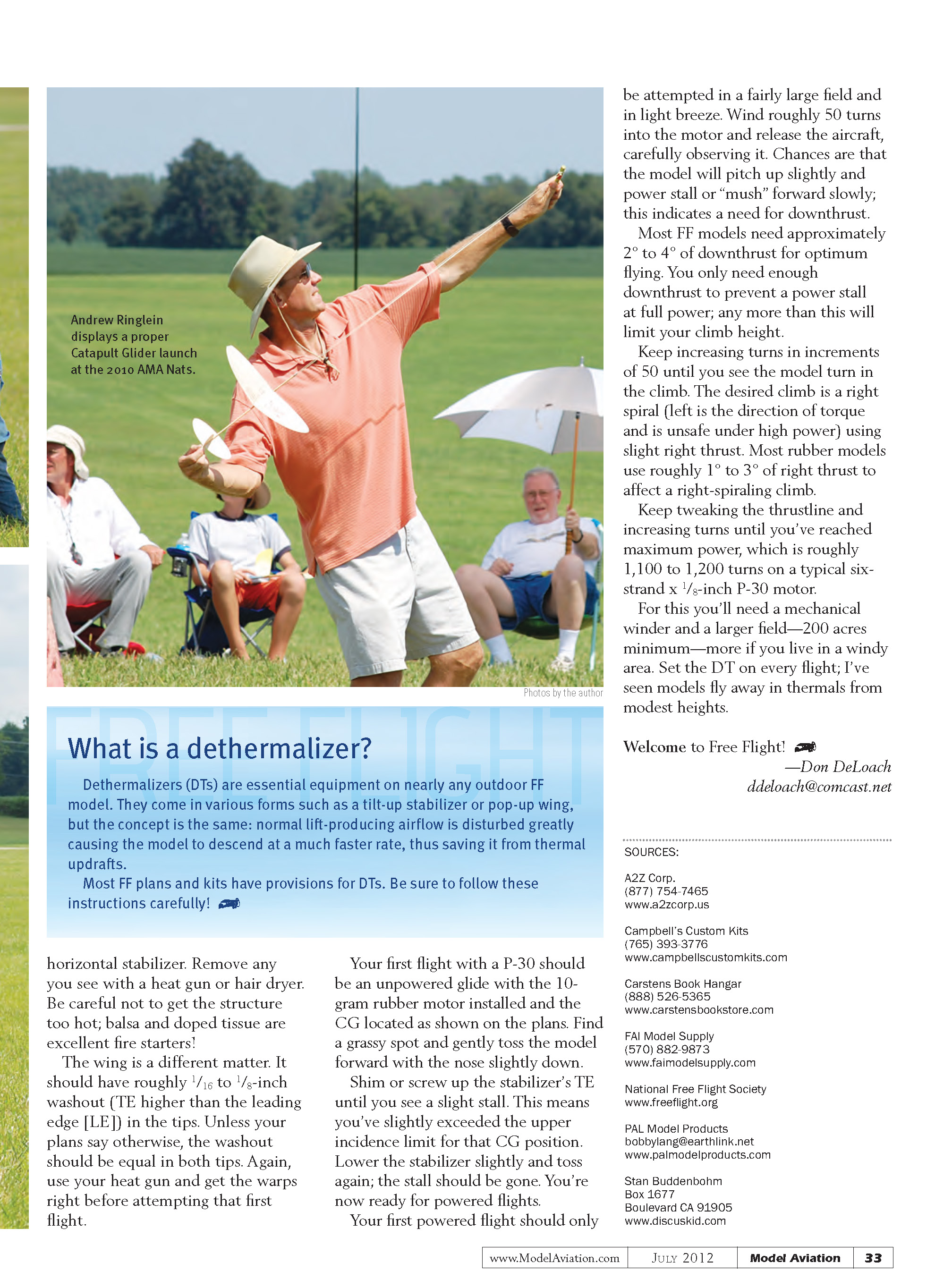
Learn more about the original form of heavier-than-air flight
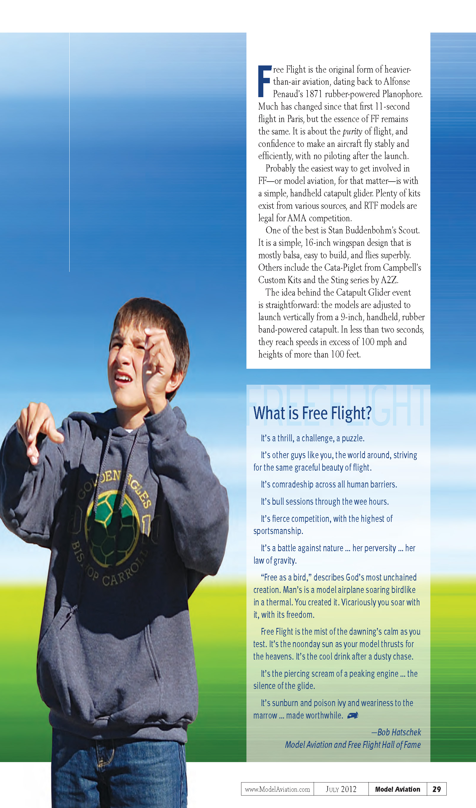
Free Flight (FF) is the original form of heavier-than-air aviation, dating back to Alphonse Penaud’s 1871 rubber-powered Planophore. Much has changed since that first 11-second flight in Paris, but the essence of FF remains the same: the purity of flight and the challenge of making an aircraft fly stably and efficiently with no piloting after launch.
Catapult gliders: an easy entry
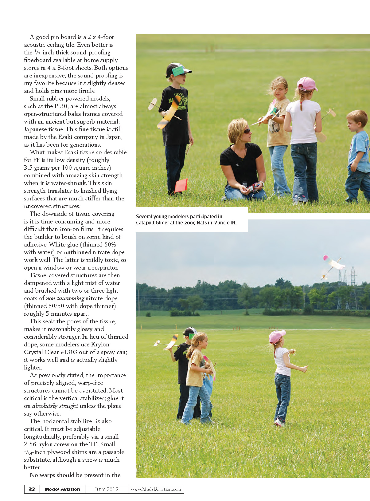
Probably the easiest way to get involved in FF—or model aviation, for that matter—is with a simple, handheld catapult glider. Plenty of kits exist from various sources, and RTF models are legal for AMA competition. Examples include:
- Stan Buddenbohm’s Scout — a simple 16-inch wingspan design, mostly balsa, easy to build, and excellent flying.
- Cata-Piglet from Campbell’s Custom Kits.
- The Sting series by A2Z.
The Catapult Glider event uses models adjusted to launch vertically from a 9-inch handheld rubber-band-powered catapult. In less than two seconds they can reach speeds in excess of 100 mph and heights over 100 feet. After the launch the magic happens: the gliders slow at the top, the nose drops, and they transition into slow, circling, floating glides of roughly 5 mph. From a good launch, a well-trimmed catapult glider can remain aloft for approximately 90 seconds without thermal help.
Catapult gliders aren't difficult to adjust for flight if you understand the dynamics involved:
- Rudder offset controls roll/transition and is effective mainly at launch speeds.
- Stabilizer tilt and center of gravity (CG) are generally effective during the glide.
- Incidence changes affect both launch and glide.
Initial flight trimming
- Set the CG at the plans location and hand-glide the model in calm conditions.
- Look for a gradual glide turn (left or right depending on trim) with no tendency to spin or dive.
- If the model dives, add incidence (stabilizer trailing edge [TE] up) until the model is at the edge of a stall.
- If the model spins or banks drastically, you probably have a crooked fin or wing.
- A proper launch should be pitched up roughly 45° to 60° and banked right about 45° for a right-handed flier. Reverse for left-handed fliers.
Powered FF: P-30 — a classic starter
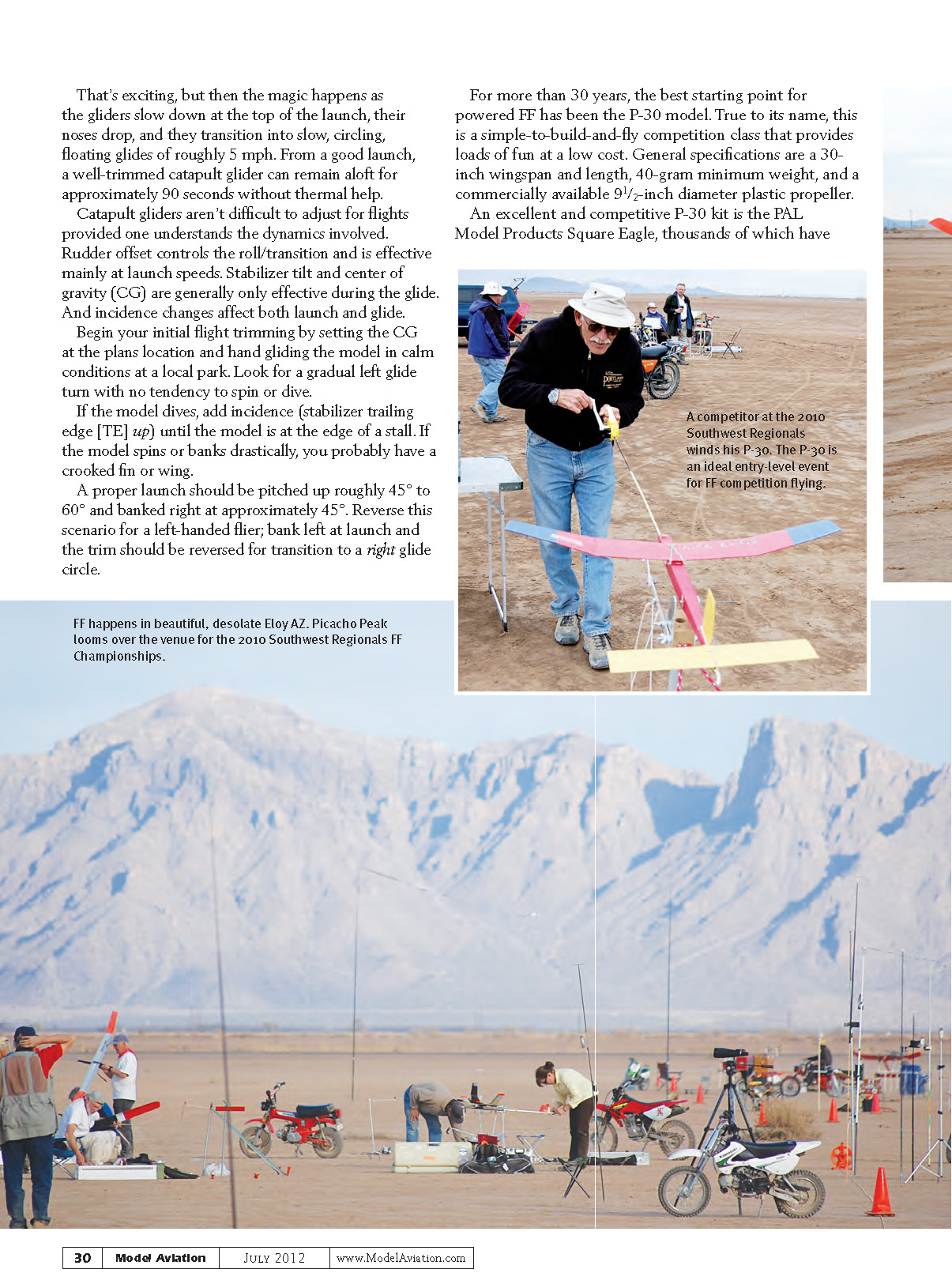
For more than 30 years, the P-30 model has been the best starting point for powered FF. True to its name, it’s a simple-to-build-and-fly competition class that’s fun and low cost. General specifications:
- 30-inch wingspan and length
- 40-gram minimum weight
- commercially available 9½-inch diameter plastic propeller
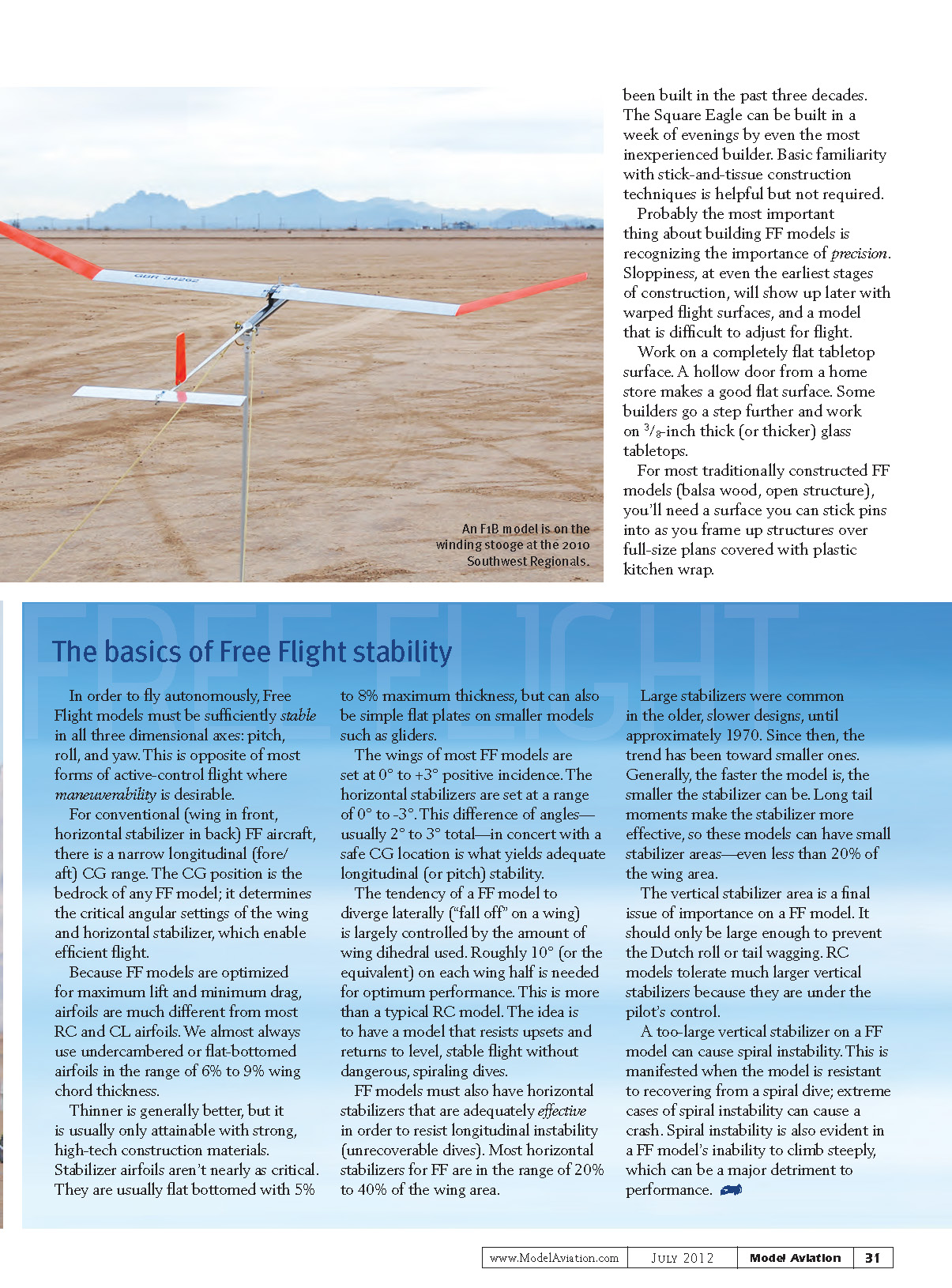
An excellent P-30 kit is the PAL Model Products Square Eagle; thousands have been built in the past three decades. A Square Eagle can be built in a week of evenings by even an inexperienced builder. Basic familiarity with stick-and-tissue construction helps but is not required.
Work surfaces and the importance of precision
Probably the most important thing about building FF models is recognizing the importance of precision. Sloppiness, even at the earliest construction stages, will show up later as warped flight surfaces and a model that is difficult to trim.
Work on a completely flat tabletop surface. Suggestions:
- A hollow door from a home store makes a good flat surface.
- Some builders use a 3/8-inch (or thicker) glass tabletop.
- A good pin board is a 2 x 4-foot acoustic ceiling tile.
- Even better is 1/2-inch sound-proofing fiberboard (available in 4 x 8-foot sheets)—slightly denser and holds pins more firmly.
For most traditional FF models (balsa wood, open structure), you’ll need a surface you can stick pins into as you frame structures over full-size plans covered with plastic kitchen wrap.
The basics of Free Flight stability
In order to fly autonomously, Free Flight models must be sufficiently stable in all three axes: pitch, roll, and yaw. This is the opposite of most active-control flight forms, where maneuverability is desirable.
For conventional (wing in front, horizontal stabilizer in back) FF aircraft, there is a narrow longitudinal (fore/aft) CG range. The CG position is the bedrock of any FF model; it determines the critical angular settings of the wing and horizontal stabilizer that enable efficient flight.
Because FF models are optimized for maximum lift and minimum drag, their airfoils differ from most RC and control-line airfoils. We almost always use undercambered or flat-bottomed airfoils in the range of 6% to 9% wing chord thickness. Thinner airfoils are generally better but often require stronger, higher-tech construction materials. Stabilizer airfoils aren’t as critical; they are usually flat-bottomed with 5% to 8% maximum thickness and can be simple flat plates on small models like gliders.
Typical angle settings:
- Wing incidence: 0° to +3°
- Horizontal stabilizer incidence: 0° to -3°
This difference of about 2° to 3°, together with a safe CG location, yields adequate longitudinal (pitch) stability.
Lateral stability (resisting falling off a wing) is largely controlled by wing dihedral. Roughly 10° (or the equivalent) on each wing half is needed for optimum performance—more than a typical RC model. The idea is a model that resists upsets and returns to level flight without dangerous spiral dives.
Horizontal stabilizers must be adequately effective to resist longitudinal instability (unrecoverable dives). Most FF horizontal stabilizers range from 20% to 40% of the wing area. Older, slower designs used large stabilizers until about 1970; since then the trend has been toward smaller ones. Generally, the faster the model, the smaller the stabilizer can be. Longer tail moments make stabilizers more effective, allowing even less than 20% stabilizer area in some designs.
Vertical stabilizer area should be only large enough to prevent Dutch roll or tail wagging. RC models tolerate much larger vertical stabilizers because they are actively controlled. A too-large vertical stabilizer on a FF model can cause spiral instability—resistance to recovering from a spiral dive, which can lead to crashes—or an inability to climb steeply.
Materials and covering
Small rubber-powered models (such as P-30) are almost always open-structured balsa frames covered with Japanese tissue made by the Esaki company. Esaki tissue is desirable because of its low density (roughly 3.5 grams per 100 square inches) combined with strong skin when water-shrunk. The finished flying surfaces become much stiffer than the uncovered structure.
Covering with tissue is time-consuming and more difficult than iron-on films. It requires brushing on adhesive. Options:
- White glue thinned 50% with water.
- Unthinned nitrate dope (mildly toxic—use ventilation or a respirator).
After the tissue is attached, dampen with a light mist of water and brush two or three light coats of non-tautening nitrate dope (thinned 50/50 with dope thinner) roughly 5 minutes apart. This seals pores, adds gloss, and increases strength. As an alternative to thinned dope, some modelers use Krylon Crystal Clear #1303 spray, which works well and is slightly lighter.
Building and alignment
The importance of precisely aligned, warp-free structures cannot be overstated:
- Vertical stabilizer: glue it on absolutely straight unless the plans say otherwise.
- Horizontal stabilizer: must be adjustable longitudinally, preferably via a small 2-56 nylon screw on the TE. Small 1/64-inch plywood shims are a passable substitute.
- Remove any warps in the horizontal stabilizer with a heat gun or hair dryer—be careful not to overheat; balsa and doped tissue are fire hazards.
Wing tips should have roughly 1/16- to 1/8-inch washout (TE higher than the leading edge). Unless your plans say otherwise, washout should be equal in both tips. Correct warps before attempting the first flight.
Flying a P-30: first flights and trimming
Your first flight with a P-30 should be an unpowered glide with the 10-gram rubber motor installed and the CG located as shown on the plans:
- Find a grassy spot and gently toss the model forward with the nose slightly down.
- Adjust (shim or screw) the stabilizer’s TE until you see a slight stall—this means you’ve slightly exceeded the upper incidence limit for that CG position.
- Lower the stabilizer slightly and toss again; the stall should be gone. You’re now ready for powered flights.
First powered flight guidance:
- Attempt the first powered flight in a fairly large field and light breeze.
- Wind roughly 50 turns into the motor and release the aircraft, carefully observing it.
- If the model pitches up and power stalls or “mushes” forward slowly, you need downthrust.
Most FF models need approximately 2° to 4° of downthrust for optimum flying—just enough to prevent a power stall at full power; more downthrust will limit climb height. Increase turns in increments of 50 until the model turns in the climb. The desired climb is a right spiral (left is the direction of torque and is unsafe under high power) using slight right thrust. Most rubber models use roughly 1° to 3° of right thrust to produce a right-spiraling climb.
Keep tweaking the thrust line and increasing turns until reaching maximum power—roughly 1,100 to 1,200 turns on a typical six-strand x 1/8-inch P-30 motor. For this you’ll need a mechanical winder and a very large field—200 acres minimum—more if you fly in a windy area. Set the dethermalizer (DT) on every flight; models can fly away in thermals from modest heights.
Welcome to Free Flight!
—Don DeLoach
What is a dethermalizer?
Dethermalizers (DTs) are essential equipment on nearly any outdoor FF model. They come in various forms such as a tilt-up stabilizer or pop-up wing, but the concept is the same: normal lift-producing airflow is disturbed greatly, causing the model to descend much faster and thus escape thermal updrafts.
Most FF plans and kits have provisions for DTs—be sure to follow these instructions carefully!
Transcribed from original scans by AI. Minor OCR errors may remain.

