
Bell P-63 Kingcobra - 2004/08
by Mark Fineman
Often overlooked warbird makes great FAC WW II Mass Launch design
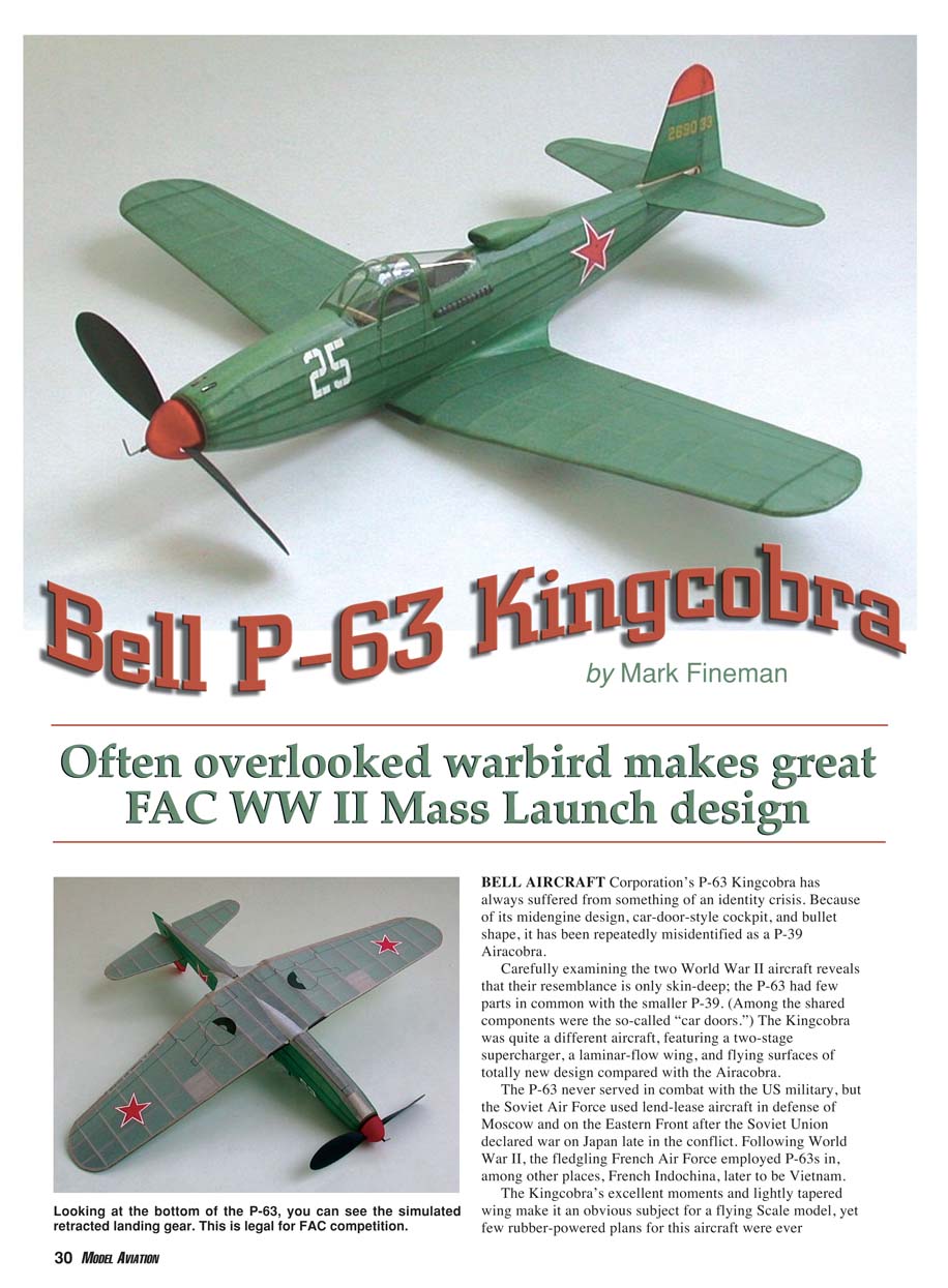
BELL AIRCRAFT Corporation’s P-63 Kingcobra has always suffered from something of an identity crisis. Because of its midengine design, car-door-style cockpit, and bullet shape, it has been repeatedly misidentified as a P-39 Airacobra.
Careful examination of the two World War II aircraft reveals that their resemblance is only skin-deep; the P-63 had few parts in common with the smaller P-39. (Among the shared components were the so-called "car doors.") The Kingcobra was quite a different aircraft, featuring a two-stage supercharger, a laminar-flow wing, and flying surfaces of totally new design compared with the Airacobra.
The P-63 never served in combat with the US military, but the Soviet Air Force used lend-lease aircraft in defense of Moscow and on the Eastern Front after the Soviet Union declared war on Japan late in the conflict. Following World War II, the fledgling French Air Force employed P-63s in, among other places, French Indochina, later to be Vietnam.
The Kingcobra’s excellent moments and lightly tapered wing make it an obvious subject for a flying scale model, yet few rubber-powered plans for this aircraft were ever published. To the best of my knowledge, there were no P-63 kits either. The 22" version featured here was intended primarily for the Flying Aces Club (FAC) WW II Mass Launch event. FAC mass-launch rules permit retractable gear to be modeled in the "up" position, but fidelity to scale must be maintained. The full-scale P-63 featured a hub-firing 37 mm cannon and four .50-caliber machine guns, two of which were mounted in gondolas beneath the wings. Photos show that the latter were sometimes removed from Soviet Kingcobras, and I carried out that practice on my model. The wing guns are shown on the plans for anyone who would like to include the gondolas on his or her model.
Construction
The P-63 model’s design should be familiar to anyone who has ever built a World War II model designed by Earl Stahl, Comet, and many others.
Flying Surfaces
The curved wingtips and the rudder tip are formed from three laminations of 1/32" x 1/16" balsa. A good way to make the laminations is to glue copies of the curved areas of the plans onto illustration board, cut them to their inside dimensions, and apply wax to their edges (candle wax works well). Pin the forms firmly to your building board. Soak the lengths of balsa in extremely hot water for a few minutes, and then carefully bend three laminations to the outside of a form, applying slightly diluted white glue between layers. Use straight pins to hold the balsa "sandwich" to the building board while it dries—probably overnight. Carefully remove the dried laminations from the forms, and trim them for assembly into the flying surfaces.
The wing spars are on the top surface of the wing. Build the wing halves separate, and then block up each wingtip 1-1/2". Sand the ends of the spars, the leading edges (LEs), and the trailing edges (TEs) so they will form a tight joint when the wing halves are connected. When the halves are joined correctly, glue them together with a few drops of cyanoacrylate. The instant glue is better for this operation than ordinary model-airplane glue because the cyanoacrylate will not pull on the joint as it dries, thereby adding dihedral.
Fuselage
Build the fuselage using the time-tested half-shell method. Construct each former in halves, separated along the vertical midline. Lay the top and bottom longerons directly on the plans. Glue the formers into place starting at the rear of the fuselage.
You should use a small metal triangle or square with a true right angle to make certain that each former is glued in at right angles to the building board. Never trust this alignment to the eye! If the former halves are properly aligned with the longerons, everything else will fall into place.
Once the formers have dried, systematically add the remaining stringers to create a complete fuselage half. When this assembly is dry, remove the fuselage half from the building board and add the complementary former halves and stringers on the other side to complete the structure.
The canopy-area construction is unusual. For the sake of appearance, the canopy brace is formed from two laminations of basswood. Balsa should also work here. The clear canopy aft of the canopy brace is a simple acetate sheet (the pattern is included on the plans). You must vacuum-form or plunge-form the more complex clear canopy to the front of the brace, which requires that you fashion a mold.
The accompanying framework photos show that I filled several stringer bays at the front of the fuselage with 1/16" balsa scrap. This technique strengthens and smoothes the nose contours and adds nose weight, which is usually needed anyway. It also makes it easier to make the indentations for the two fuselage-mounted machine-gun muzzles.
Make sure you sand this sheeted area smooth and paint it with two coats of sanding sealer before you apply the tissue.
Finishing
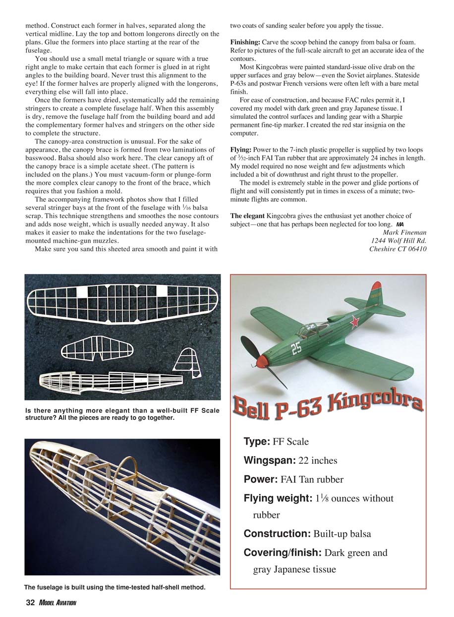
Carve the scoop behind the canopy from balsa or foam. Refer to pictures of the full-scale aircraft to get an accurate idea of the contours.
Most Kingcobras were painted standard-issue olive drab on the upper surfaces and gray below—even the Soviet airplanes. Stateside P-63s and postwar French versions were often left with a bare metal finish.
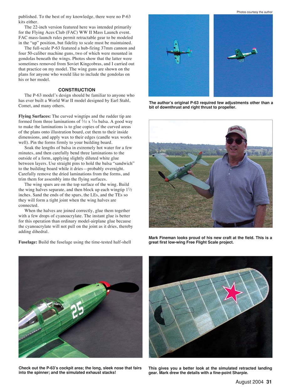
For ease of construction, and because FAC rules permit it, I covered my model with dark green and gray Japanese tissue. I simulated the control surfaces and landing gear with a Sharpie permanent fine-tip marker. I created the red star insignia on the computer.
Flying
Power to the 7" plastic propeller is supplied by two loops of 3/32" FAI tan rubber that are approximately 24" in length. My model required no nose weight and few adjustments, which included a bit of downthrust and right thrust to the propeller.
The model is extremely stable in the power and glide portions of flight and will consistently put in times in excess of a minute; two-minute flights are common.
The elegant Kingcobra gives the enthusiast yet another choice of subject—one that has perhaps been neglected for too long.
MA
Mark Fineman 1244 Wolf Hill Rd. Cheshire CT 06410
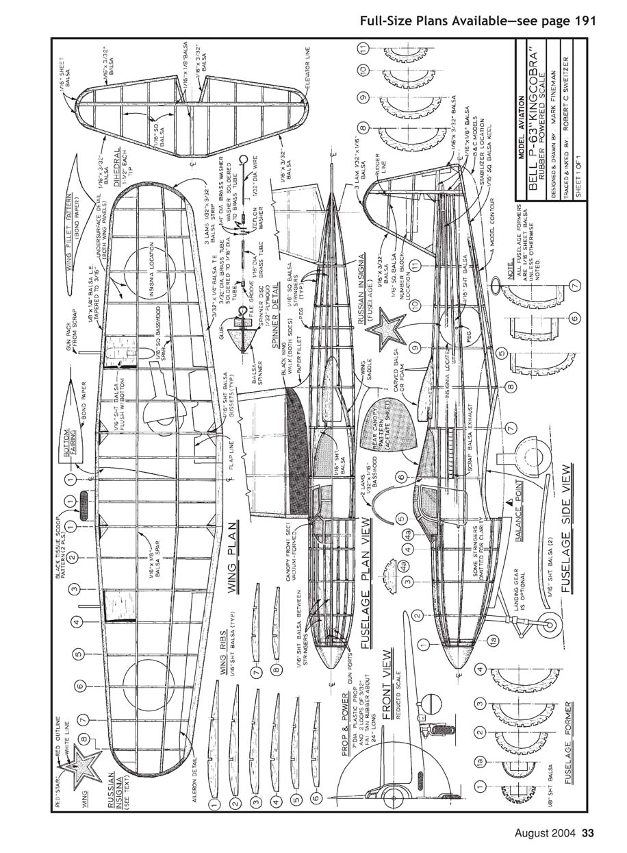
Full-Size Plans Available—see page 191
This page contains full-size plans and component labels for the Bell P-63 Kingcobra (no additional article prose). Visible plan labels and callouts include:
- Wing Plan
- Wing Ribs
- Wing Fillet Pattern
- Aileron Detail
- Insignia Location / Russian Insignia
- Fuselage Plan View
- Fuselage Side View
- Fuselage Formers
- Front View
- Spinner Detail
- Prop & Power
- Balance Point
- Landing Gear (optional)
- Various material callouts (e.g., 1/16" sheet balsa, 1/32" x 1/16" balsa laminations)
- Numbered part references and section outlines
No continuing article text appears on this scanned page.
Transcribed from original scans by AI. Minor OCR errors may remain.

