
Better Props for Formula 1
Harold deBolt
New engines have changed so dramatically that matching correct props to them has
THIS ARTICLE is dedicated to the average Formula I racing pilot, and hopefully my offering of assistance will help improve his performance. So all you Bob Violetts and Terry Prathers, keener competitive racing may be in the offing!
As far as speed is concerned, the past year has been a paradox for a great many Formula I pilots. Our powerful engines cannot be improved to a much greater extent, so we are fairly equal equipment-wise. The question now arises, "How come two pilots with parallel equipment and ability wind up miles apart in performance?"
Most of the year, I, too, pondered "why," finally asking one of the leading competitors that very question. After a review of my equipment, he clued me to the fact that speed stems from propeller efficiency, for the difference between average speed and top speed depends entirely upon the particular prop used. By merely tailoring a recommended stock prop a bit, average speed will be sustained quite easily, but to obtain top speed, one has to find the "right prop," work, adjust and experiment with it. Never before has so much speed been gained from a critical match of propeller to the rest of one's equipment.
Today's average racing speed is still about the same as it was several years ago. In contrast, top speed has increased drastically. New engines have changed so dramatically, that matching right props to them is now a whole new ball game. Previously, much more propeller was used in every respect than is presently used, so speed was easy to come by. Today, speed is more difficult to realize because we are forced to use smaller props to match the change in engines. Therefore, speed increase relies on propeller efficiency, not just size alone.
To analyze the situation, the answer is become a whole new ball game—and the name of the game is prop efficiency.
twofold: engine and propeller design. New engines develop more horsepower but less torque than old-style engines. Thus, a much smaller prop is needed to maintain the required rpm that provide horsepower. A propeller should be designed to fit an airplane and the amount of power to turn the propeller then chosen. Our approach is backwards. Rules fix the size of an airplane and the amount of power before one fits a propeller to it! An ideal size Form-I airplane propeller would be many times larger than props we are forced to use. Therefore, anything that can be done at all to get a larger prop on an airplane would show a dramatic increase in speed performance, even though prop size increase may not be very large. For example, older engines with less hp had more torque, allowing the use of larger props, resulting in speeds similar to that attained with higher rpm and horsepower engines.
Frankly, we are handcuffed to engines whose designs require use of horsepower rather than torque. While we can do nothing about engines, it is conceivable that much can be accomplished with propellers to help us gain speed. Engines and airplanes have advanced extensively in recent years, but propeller development has unfolded only gradually. Today, prop manufacturers give us better workmanship, materials and size choice but fail to delve into any real research to improve their designs.
Years ago, Tony Grish came forth with the Tornado prop, a dramatic improvement over previous offerings from others. His design resulted from considerable research. Tony developed the Tornado through the use of a wind tunnel, a static-thrust machine, another machine that checked thrust at speed, plus extensive flight testing. Grish will long be remembered for his dedication to our sport's progress. Regretfully, there is no Tony Grish today to help solve present prop problems, so if we are to continue prop improvement, we must act for ourselves.
Presently, propeller design is a mystery to many of us simply because very little information is readily available. It is common belief that props are difficult to make from scratch, but with experience, one can produce a complete prop in little more time than it takes to rework a commercial prop.
This article is intended to provide information about propellers for the layman to experiment with, to perhaps discover what really does make that "special prop" so great. It is safe to assume that special props are far from being the ultimate. Certainly, some realistic experimental work along the way will uncover something better. I will attempt to explain what a propeller actually is, what constitutes a better propeller, what the design parameter should be for a speed propeller, plus results of my personal experimentation with basic commercial props available.
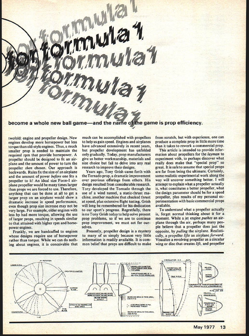
To understand what a propeller actually is, forget normal thinking about it for a moment. While a jet engine pushes an airplane through the air, perhaps many people believe that a propeller does just the opposite, by pulling the airplane. Realistically, a propeller lifts an airplane forward. Visualize a revolving propeller as a circular wing or disc that creates lift, and propeller design will be easier to understand. The amount of lift or thrust developed by a disc is directly proportional to the density of it, plus the area determined by the propeller's diameter.
Density is controlled by the speed a propeller turns, how many times the blades revolve in one time segment, plus the width of the blades. Speed is a time element, so the more blade revolutions in a given time element, the denser the disc for that time. A blade develops "X" amount of lift itself. At one point on the disc's circumference, if a blade revolves 20,000 times in one minute, the lift developed is 20,000 X "X" and greater, of course.
Density is also controlled by blade width; the wider the blade, the larger the segment of the disc it covers. Efficiency of a propeller is controlled by its lift-drag ratio (L/D) which, unfortunately, gets out of proportion when blade width is greater than 12% of the diameter. As explained further in this article, most commercial speed props use a blade width of only 7%, which could be improved upon.
The obvious answer to increase speed is to simply increase rpm; however, that is limited. The more times a propeller revolves in a given time, without any forward motion, the more the air is disturbed. Propeller efficiency will suffer when rpm becomes too great, particularly if rpm does not match the forward speed of the aircraft. For example, prop rpm too high on a slow-flying model.
Tip speed is another problem created by too high rpm. When an airfoil approaches approximately 3/4 of the speed of sound, shock waves begin to generate, creating greatly disturbed air, plus considerable drag. Shock waves can also cause a propeller blade to flutter and become useless. Tip speed must be considered when choosing the operating rpm of the propeller. For example, tip speed of a 9-in. diameter propeller at 22,000 rpm is 589 mph and in the sonic range.
With maximum rpm restricted, the only answer we have to obtain more aircraft speed is to increase the propeller disc size or "fill in the disc" better through the use of a wider prop blade and/or increase propeller pitch.
What is pitch? Simply stated, pitch is the distance a propeller moves forward in one revolution if used in a solid substance. The more pitch a propeller has, the further forward it will move or the greater the aircraft speed if rpm are constant. However, pitch can also be compared with a wing's angle of attack, for a prop blade is also a wing. Just as a wing does, a propeller blade will stall if the angle of attack becomes too great, or the pitch is too high; however, unlike a wing, a propeller has the advantage of revolving while moving forward. Consequently, the angle of attack and the stall angle are reduced, which explains why we are able to use higher angles with props than with wings. It is clear why a lower pitch propeller will provide quicker take-off but less speed when terminal velocity is reached.
The amount of speed gained by increasing pitch is limited, not only by power available to use it but also by the stalling point of the blade. It is most interesting that the higher an inherent aircraft speed, the more pitch can be used because of higher potential forward speed. Therefore, a cleaner designed aircraft compounds itself by allowing use of more propeller pitch.
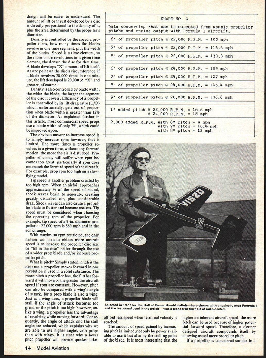
CHART NO. 1
Data concerning what can be expected from usable propeller pitches and engine output with Formula I aircraft.
6" of propeller pitch @ 22,000 R.P.M. = 100 mph 7" of propeller pitch @ 22,000 R.P.M. = 116.6 mph 8" of propeller pitch @ 22,000 R.P.M. = 133.3 mph
6" of propeller pitch @ 24,000 R.P.M. = 109 mph 7" of propeller pitch @ 24,000 R.P.M. = 127 mph 8" of propeller pitch @ 24,000 R.P.M. = 145.4 mph
9" of propeller pitch @ 20,000 R.P.M. = 136.6 mph
1" added pitch @ 22,000 R.P.M. = 16.6 mph @ 24,000 R.P.M. = 18 mph
2,000 added R.P.M. with 6" pitch = 9 mph with 7" pitch = 10.4 mph with 8" pitch = 12 mph
If a propeller is considered similar to a wing, how much lift does a prop have? A Form-I wing in flight can generate several times the aircraft's weight. It generates its greatest lift at its maximum angle of attack. If a balanced model is flown in level flight with a wing incidence at the maximum angle of attack, it will rise vertically. Would 50 mph sound logical? We know that if a Form-I nose is pointed vertically out of level flight, it will go straight up without great loss of speed. Propeller lift is far greater than lift the wing is capable of!
All well and good, but we are at a stand still if we do not realize what constitutes a better propeller. Obviously, the larger the diameter and thus, the disc size, the greater the amount of lift. Diameter increase will help if all other parameters remain constant. A 1/2-in. larger diameter will increase disc area by 12%; an excellent goal to strive for.
Disc "fill in" is controlled by rpm and blade width, therefore, props should be designed for maximum rpm within the subsonic tip-speed range. Keep the blade width as great as possible while sustaining an efficient L/D ratio.
Of course, blade airfoil should generate the greatest amount of lift possible, the only problem being, high-lift airfoils generally create considerable drag. Drag is one criterion of propeller design we should not overlook, primarily because the amount of engine power is "fixed." Thus, drag is the major reason why a propeller's maximum rpm is limited.
Drag is created by propeller size or diameter, amount of blade area, shape of the blade, airfoil used, amount of pitch and surface finish. In other words, everything used creates drag and that does nothing but detract from good performance. A study of current commercial props indicates drag reduction is the greatest possible improvement manufacturers can make in their design. Let us review all potential channels to pursue to reduce drag:
Maintaining the maximum diameter possible without reducing blade width below minimum is the greatest factor that contributes to lift, while also fitting important needs of the model.
Amount of pitch is a fixed factor in sustaining performance except for the possibility of "cheating" with pitch a bit to reduce drag. Propeller efficiency goes from 0% at the prop's hub to 100% at 2/3 station on the blade and from 100% down to zero again at the very tip. Progression is constant from the hub out, but variable from the 2/3 station out because the tip is nearly reached before lift falls off rapidly.
Blade speed is greatest at the tip because the tip has to travel much further than the hub does to complete one revolution. Propeller designers have proven the advantages of using progressive pitch. Using more pitch than needed at the 2/3 station, lesser from the hub to the 2/3 station and lesser from the tip to the 2/3 station, the average will be the true amount of pitch desired. This procedure reduces drag. Actual pitch needed is determined by terminal velocity of the model design or the point at which the drag of the design equals the amount of propeller thrust. Terminal velocity varies according to model design. A clean design will have a higher terminal velocity than a less streamlined model, thus greater propeller efficiency is realized. No data is available on exact speed of our models but some assumptions born out of mathematics can be made. When racing, we fly approximately 130 mph around the pylons, faster on the straights, slower in the turns and slower due to deceleration in the turns. Propeller pitches which we use are in the realm of reality for that speed, therefore, striving for about 7 in. pitch is a good starting point for experimentation.
Blade width helps increase propeller disc lift. For this reason, use as wide a blade as possible, as test data proves further along in this article. While blade width does not detract too much from rpm, it does add greatly to static thrust, another racing factor to be considered. The more static thrust, the greater the aircraft acceleration will be. Acceleration affects racing speeds at takeoff and coming out of turns. No big drag increase is realized by using a wider blade. Propeller designs have maximum width only at the 2/3 point and progress to absolute minimum at tip and hub, however, even with this reduction there is as much area in those sections as in typical narrow blade designs. Increasing blade width by only 10 to 20% will cause a dramatic thrust increase, therefore, width experiments are safe up to 12% of the diameter, beyond which, efficiency begins to deteriorate. Shape of the blade is imperative to tie the three necessary points together from the hub, to the 2/3 point, to the tip. Naturally, blade shape affects drag, so keep it as smooth as possible for least disturbance.
Referring back to pitch progression again, the same idea may be used with area. To reduce drag, simply decrease the area at the least efficient portions of the blade and increase the area at the 2/3 station to realize enough "average" area.
Propeller blade airfoil is one place where large drag reduction can be achieved. With a given engine, a fast fighter-type full-scale aircraft may have a semi-symmetrical airfoil in its larger diameter propeller, while a load carrying aircraft has a flat-bottom or undercambered airfoil. There is a lesson to be learned here. A semi-symmetrical airfoil has much less drag and a lower lift factor. Obviously, while in use, some blade lift is lost but, if lower drag allows a larger diameter for a given amount of power, the propeller "disc area" is increased, which really is more important than blade lift loss. When flying a load carrying aircraft, speed is not as important as the ability to lift the maximum amount of weight. It is weight that loads a propeller down, so use of a high-lift blade is most important. When flying a fighter plane, drag from the aircraft itself loads the prop more than weight does, so at higher flying speed, it is possible to achieve just as much efficiency from a streamlined airfoil. With blade efficiency being close to same and propeller "disc area" much larger, this produces a plus factor.
With 360 mph the average operating speed of a model's propeller, a range is reached where a streamlined airfoil is much more efficient than a Clark Y type because speed above 100 mph drastically increases drag from flat-bottom sections.
Finish of a propeller affects drag just as finish does with the rest of an airplane. Because of its small size and high speed in comparison with a wing, roughness has a proportionally greater effect on the propeller than on any other part of an airplane.
All of the above characteristics affect propeller performance. Assuming that propeller designers and producers have already considered good performance as one consequence of their talents, perhaps there is something more the average model-builder/flier can do on his own to increase propeller performance. Propeller engineers are aware that there are two ways pitch can be built into a propeller, having labeled them helical and progressive pitch. The amount of helical pitch is constant throughout the length of the blade. With progressive pitch a higher than desired pitch angle is used at the most efficient station of the blade. A lower than desired pitch angle is used at the least efficient stations. The average of them is the desired pitch.
Progressive pitch results in a higher propeller rpm due to the reduction in drag at the stations where prop efficiency is lowest. A comparison of thrust developed by helical and progressive pitch propellers shows that the use of some progression can be of an advantage. Progression may also be applied to the blade shape, using less area at less efficient stations, more at most efficient stations. At one time or another, Form-I pilots have all washed out the tips of a prop because progressive pitch was found to be of help. Just check stock prop performance before and after progression is added to note the improvement. Moderate progression will yield an additional 500 rpm plus cutting a few seconds racing time. It is logical to assume some really interesting prop improvements lie ahead if all ideas are applied.
I have experimented with props considerably over the years; not as extensively as I would have liked to have done, nevertheless, all results were positive. My equipment consisted of standard Formula-I aircraft, K&B engines, a good tachometer, a respectable thrust stand and "elbow grease." Consequently, my efforts never created any national records but they greatly improved my aircraft performance. Commercial props limit work expansion on them because of lack of sufficient material. One must either start from scratch or locate a more usable prop to increase performance. Both approaches will net worthwhile results.
Several charts are presented in this article to help you understand the workings of a propeller. My own test results are shown. Chart #1 indicates theoretical speeds obtained using various common propeller pitches. All results have been adjusted to 80% propeller efficiency. Chart rpm are free engine rpm in the air. Expect a pick-up of at least 10% air rpm over ground rpm. This is known as "unloading," of course. When evaluating a propeller, remember that a so called "good" prop always appears to "unload" more than one less efficient.
Simple mathematics will render several interesting things. Note speed increase as pitch is added, keeping rpm constant. Reducing drag of a given size prop will cause rpm to rise. Adding more pitch will increase mph while maintaining original rpm. At the rpm range, adding 1 in. of pitch will increase mph up to 17 miles. To gain this amount of speed while increasing rpm and keeping the same pitch, one must add 3700 rpm! We are all aware of the difficulty to gain even 500 rpm in this range, so it is logical to experiment more with props than with engines!
The chart also indicates expected performance from so called torque-type engines versus engines dependent upon pure horsepower. All figures presented stem from new horsepower type engines. Previously, torque-type engines allowed better propeller efficiency by giving equivalent air speeds at lower rpm. These engines could turn a 9 diameter X 9 pitch prop at 20,000 rpm or an equivalent of 136 mph. It is too bad that engine power cannot be increased with torque rather than rpm as that would be more applicable to a propeller.
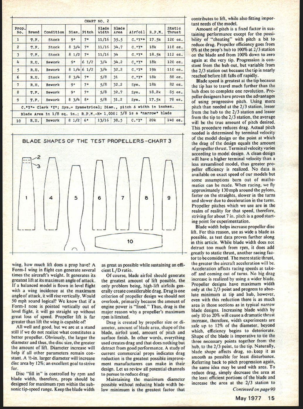
Charts #2 and #3 denote test results of several proven "good" Formula-I propellers. Those labeled "stock" are exactly that. However, sizes chosen are such that they will yield peak flight performance for stock props. "Reworked" props have been tailored according to ideas presented in this article. Primarily, diameter and/or pitch increase over acceptable stock props is strived for while keeping rpm in maximum engine horsepower range. When my extensive original prop work was completed, props were checked on an excellent Formula-I aircraft with a K & B .40 S III engine, flown and proven competitive.
Chart information presented was obtained from one running session for accurate comparisons. Results were achieved with an inferior engine running under far from ideal climatic conditions, so rpm shown is about 2,000 rpm below normal engine expectancy under better conditions.
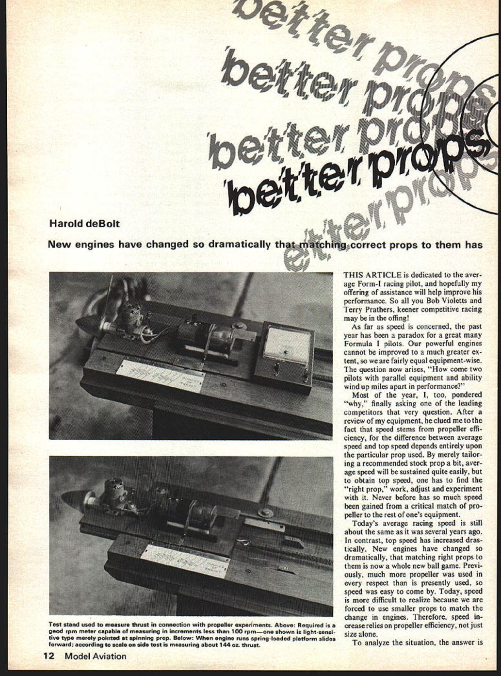
Test equipment used were a K & B S III engine, an expanded meter photo cell tachometer and a specially built thrust stand. Engine and tach were purchased items and nothing "special." The thrust stand was precision built, fulfilling a lifelong desire of mine. Although the thrust stand readings only needed to be comparative, they were accurate. Highest "speed prop" thrust reading was 144 oz. or 2 lbs.; a great deal of thrust from only a .40 cubic inch engine, indicating the outstanding work our engine manufacturers have extended to us the last few years. It is interesting to know that a stunt-type propeller yields considerably more static thrust than our best speed props.
Chart #3 is presented for evaluation of differences in tested blade shapes. No attempt has ever been made to experiment with the blade shape of one specific size propeller, however, chart comparisons indicate work in this area could be beneficial.
According to chart #2's test results, one is not expected to determine a "super prop," for frankly, the super prop is yet to be developed. The tests really show the consequences of alternating various design parameters. For example, the first three tests were made with the same prop by simply "clipping" the tips each time to reduce the diameter. The marked rpm increase indicates added horsepower, a small static thrust loss, but increased aircraft speed. Remember, the test was conducted by starting with "too much" prop, so the same improvement can be expected using the "right size" prop in the beginning. Note the large static thrust increase gained with a wider blade width. Such has proven to be most beneficial in actual racing.
The symmetrical airfoil experiments for drag reduction are most interesting. By changing to a lower drag airfoil, diameter and pitch are increased without horsepower loss. Symmetrical airfoil props have not been used in actual race performances as yet, but flight tests indicate they show great promise for profitable future development.
In conclusion, the purpose of this article is to hopefully incite more intelligent speed propeller experimentation in our field. Past racing performances of too many of us have proven that considerably more propeller efficiency improvement is sorely needed nation-wide! If we are to "break the sound barrier" someday, we must do the work ourselves, so fellow racers, let's all get up and go!
Transcribed from original scans by AI. Minor OCR errors may remain.

