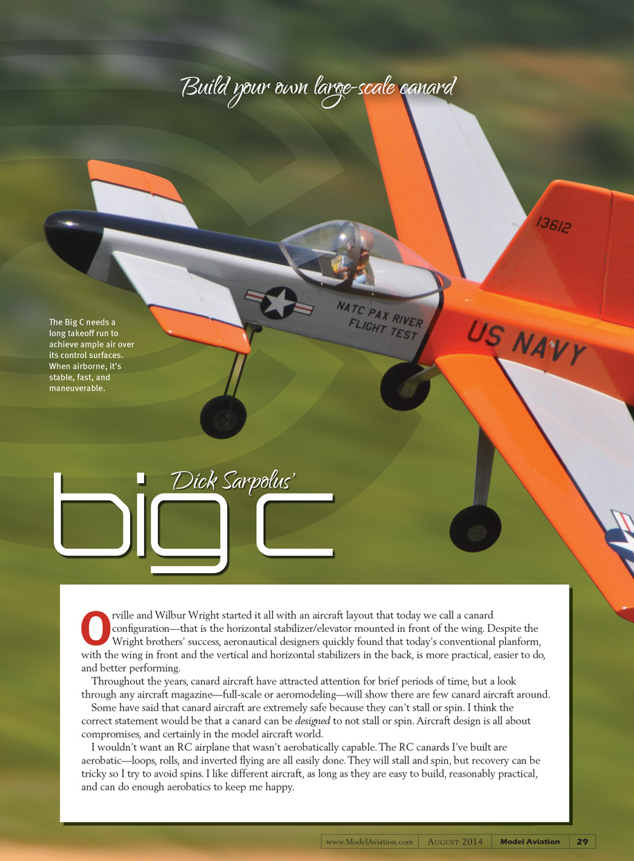
08BigC.lt1.doc
[Dick Sarpolus’s Big C]
[Build your own Giant Scale canard]
[author: Dick Sarpolus]
[Photos by the author]
[sidebar in text file]
[no additional callouts]
SPECIFICATIONS
Type: Aerobatic sport canard
Wingspan: 84 inches
Wing area: 1,200 square inches
Stabilizer area: 260 square inches
Length: 60 inches
Weight: 16-19 pounds
Wing loading: 33 ounces per square foot
Engine: Quadra 41
Propeller: Zinger 18 x 10 pusher
Finish: UltraCote
Construction: Balsa and plywood; foam wing cores
Orville and Wilbur started it all with an aircraft layout that today we call a canard configuration—that is the horizontal stabilizer/elevator mounted in front of the wing. Despite the Wright brothers’ success, aeronautical designers quickly found that today’s conventional planform with the wing in front and the vertical and horizontal stabilizers in the back is more practical, easier to do, and better performing.
Throughout the years canard aircraft have attracted attention for brief periods of time, but a look through any aircraft magazine—full-scale or aeromodeling—will show there are few canard aircraft around.
Some have said that canard aircraft are extremely safe because they can’t stall or spin. I think the correct statement would be that a canard can be designed to not stall or spin. Aircraft design is all about compromises, and certainly in the model aircraft world.
I wouldn’t want an RC airplane that wasn’t aerobatically capable. The RC canards I’ve built are aerobatic—loops, rolls, and inverted flying are all easily done. They will stall and spin, but recovery can be tricky so I try to avoid spins. I like different aircraft, as long as they are easy to build, reasonably practical, and can do enough aerobatics to keep me happy.
Electric power would be ideal for a canard layout instead of employing a heavy engine. With a relatively lightweight motor in the rear and the battery pack in the nose, proper balance would be easily achieved.
I knew the Quadra engine I planned to use was on the heavy side, but I like Quadras and wanted a gas-engine-powered canard. Other issues to address include sufficient ground clearance for the propeller in the rear and the vulnerability of the horizontal stabilizer in the front of the fuselage.
Despite the problems with a canard layout, it interests and fascinates aircraft enthusiasts who like the unusual. I’ve built half a dozen canards throughout the years. My friend, Pete Mularchuk Jr., wanted an aerobatic canard for an interesting project.
I laid out a large, gas-engine version and cut out the parts. Pete started construction, but turned it back over to me for the final labor. I knew a heavy gas engine wasn’t the best choice for this airplane, but I was determined to make it work.
The wing is foam core, and the fuselage top blocks are sheeted foam cores. The fuselage is typical balsa, plywood doublers, and plywood bulkheads. I powered the prototype with a Quadra 41 engine, turning an 18 x 10 Zinger pusher propeller. A lighter engine would mean less nose weight required for a lighter airplane, and even better performance.
Construction
I used standard sizes of balsa and plywood, along with hot-wire-cut foam cores for the wings and fuselage top blocks. There are a number of mail order sources to supply the balsa and plywood needed.
I used paper patterns to cut out the wood parts. I drew around the patterns onto the plywood or balsa with a ball point pen and cut out the parts with my band saw or scroll saw.
The template patterns for the foam core parts are on the plans. I made templates from 3/32 plywood and cut the foam with a basic hot-wire bow of nichrome or stainless wire, and a Variac transformer for the power supply. You can also order all of the foam parts from Robin’s View Productions.
A few slots had to be cut in the wing cores for the partial plywood ribs and the plywood dihedral brace/wing joiner. Additional foam should be cut out for the plywood landing gear mounting pieces.
I doubled the number of 1/4 plywood gear mount pieces to have more wood to drilled and tapped for the 1/4-20 nylon bolts that retain the sheet aluminum landing gear. I sheeted the wings with 3/32 balsa, edge-glued from 3-inch or 4-inch-wide sheets to obtain the necessary area.
I sanded the edges of the sheets for a good fit, taped the sheets together for the width, flipped the wood over, opened the taped joint like a hinge over the edge of the workbench, and applied the glue one joint at a time.
With the wood flat on the workbench, I scraped the excess glue from the joint with a putty knife and weighted the wood down until the glue dried. I block sanded the sheeting smooth before applying it to the foam cores.
I’ve used Dave Brown’s Southern Sorghum contact cement for years to put balsa sheeting on foam cores. There are other adhesives including thinly spread epoxy or spray contact cement. Be sure to experiment on scrap foam if you use anything that isn’t sold specifically for this purpose. Many contact cements will melt the foam.
With the wing cores sheeted top and bottom, I sanded the LE square, glued on a balsa strip, and planed and sanded it to shape. I cut the slot through the LE for the plywood wing mounting tab, which was glued in place after the wing had been fitted to the fuselage. Don’t forget to burn the holes through the cores for the aileron servo extension cables before joining the wing panels.
I wrapped the center section joint with heavy fiberglass cloth and epoxy, scraping the excess epoxy off with a piece of cardboard. I cut the ailerons from the sheeted wing panels, trimmed them down to allow for the balsa edging, and sanded them to shape. They’re hinged along the centerline. I cut recesses in the wing’s lower surface and epoxy in plywood mounts for the aileron servos.
I used firm or hard balsa for the two fuselage sides, edge gluing and splicing the wood to achieve the correct size. With the canard layout, I used full-length 1/16 plywood doublers inside the 1/8 balsa sides.
I glued the plywood doublers, wing saddle doublers, and lower edge strips to the two side pieces. I like a thick, strong firewall so I epoxied a piece of 1/4 and a piece of 1/8 plywood together.
With one fuselage side flat on the workbench, I epoxied the firewall and the three bulkheads in front of it, perpendicular to that side. I glued the second side to those bulkheads and further secured it with several small screws through the sides and into the firewall edges.
I added the plywood wing bolt plate, and pulled the front ends together with the bulkheads in place. I fitted the top foam blocks to the fuselage structure, sanding the foam so the sheeting would be flush with the side pieces. I used soft 1/8 balsa for the top sheeting, gluing it to the foam with contact cement and then epoxying the top blocks in place on the fuselage structure. I added the bottom sheeting after all of the linkage and hardware had been fitted.
I aligned the wing to the fuselage and made sure the wing mounting tab fit well into the fuselage bulkhead cutout when the wing is seated. I drilled and tapped the plywood wing mounting plate for the two 1/4-20 nylon bolts that hold the wing in place.
With the wing mounted on the fuselage, I added the horizontal stabilizer, aligned it with the wing, and glued it in place. I made a cutout in the middle of the stabilizer to accept the two elevator servos and reinforced that area with 1/8 plywood.
I cut a slot through the fuselage top block to accept the vertical fin and added some balsa bracing internally below the top block to reinforce the fin mounting. I recessed the control surfaces to accept plywood mounting tabs for the nylon control horns going onto the elevators, ailerons, and rudder. I used all 4-40 control hardware.
I added a plastic canopy purchased from Fiberglass Specialties. The company has a wide range of plastic canopies and fiberglass cowls.
The fuel tank was installed slightly ahead of the firewall. Brass tubing with a 180° bend leads the fuel line back to the engine.
Proper balance is important with a canard—just as with any airplane—and even with the radio battery positioned as far forward as possible, I had to add lead to the nose for proper balance. Because the fuel tank is in the rear, the proper balance point had to allow for the weight of the fuel. The airplane will be balanced at takeoff, and as the fuel is burned, the model will become more nose-heavy. Hey, the Big C is a canard; that’s the way it is.
I hollowed out a cavity in the nose block to get the added weight as far forward as possible. I epoxied .44 caliber lead bullets in the nose cavity. I started out with the balance point as shown on the plans.
I installed a Quadra engine turning a Zinger 18 x 10 pusher propeller. Zinger makes pusher propellers in a wide range of sizes. A 16 x 10 three-blade propeller would do an equally good job and provide more ground clearance, but I don’t know if such a propeller is available. If not, I bet Zinger could make one. If you use an engine that runs in the opposite direction, you’ll be able to use standard propellers.
Now for some nose gear comments: the main landing gear, formed of sheet aluminum, has to provide sufficient propeller clearance. You don’t want to take off too steeply, or land with the nose too high, to avoid hitting the propeller.
The higher you can position the engine’s thrustline and the smaller the propeller you can use, the lower the landing gear can be. In any event, the nose gear will probably be long. The construction of the nose gear will also depend on the surface of your flying field.
On a hard surface, the nose gear will not tend to be bent back so much. In the tough, fairly high grass I fly from, the drag of the grass demands a strong, stiff nose gear. I first tried a nose gear bent from a single piece of 1/4 music wire.
With the largest K&S coil bending tool, it wasn’t too hard to bend up a gear with two coils from the 1/4 wire. I used three standard nylon nose gear steering blocks and drilled them out for the 1/4 wire.
On a hard surface, I think this would have been fine. On the grass field, the nose gear bent back so far during the takeoff run that the airplane wouldn’t launch. I also needed a large, stiff nose wheel; I used 4-inch wheels. Retractable landing gear would have been great, too.
I made a double strut nose gear of 1/4 wire—two vertical pieces, two coils in each one, and a few steel blocks cut from 1/2-inch square stock, drilled and tapped for setscrews, to hold things together. It’s heavier, but it worked fine.
I thought this configuration was overkill, so I created another gear from double 3/16-wire struts. If the grass isn’t too long or tough, I think that will work fine. I couldn’t find the necessary gear commercially available, so you may have to do some heavy-duty wire bending.
After a few takeoff attempts that didn’t work, I was rethinking this canard stuff, but with the heavy-duty, double-strut nose gear, the airplane tracked straight down the field, lifted off easily, banked and turned tightly to come back over the field with a solid feel, did a nice-looking roll, and climbed out steeply. It was all worthwhile!
The Big C’s takeoff run is long because the canard control surface has to get up to speed. There’s no propeller blast over the surfaces.
Once in the air, the Big C is stable, quite fast, and maneuverable. I land with some power on and don’t try for a nose-up flare. Remember, the propeller is at the rear.
The Big C performs nice, easy rolls and loops, tight turns, and is stable in inverted flight. I started with a nose-heavy balance point and have gradually removed nose weight. I haven’t yet tried spins, but I expect recovery to require added power and down-elevator—I hope.
This Big C looks really cool flying by. Always keep in mind that the little end is in the front and if you do spins, it’s up to you to figure out how to recover. Remember, this stuff is fun![dingbat]
—Dick Sarpolus
rsarpolus2@comcast.net
SOURCES:
Fiberglass Specialties
www.fiberglassspecialtiesinc.com
Robin’s View Productions
robinhunt@rcn.com
K&S Precision Metals
www.ksmetals.com