
Big Punkin - 2005/03
by Dave Robelen
RC electric-powered small-field fun is only two wings away
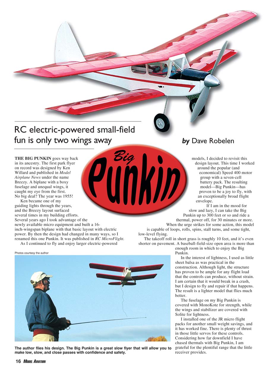
THE BIG PUNKIN goes way back in its ancestry. The first park flyer on record was designed by Ken Willard and published in Model Airplane News under the name Breezy. A biplane with a boxy fuselage and unequal wings, it caught my eye from the first. No big deal? The year was 1955!
Ken became one of my guiding lights through the years, and the Breezy layout surfaced several times in my building efforts. Several years ago I took advantage of the newly available micro equipment and built a 16-inch-wingspan biplane with that basic layout with electric power. By then the design had changed in many ways, so I renamed this one Punkin. It was published in RC MicroFlight.
As I continued to fly and enjoy larger electric-powered models, I decided to revisit this design layout. This time I worked around the popular (and economical) Speed 400 motor group with a seven-cell battery pack. The resulting model—Big Punkin—has proven to be a joy to fly, with an exceptionally broad flight envelope.
If I am in the mood for slow and lazy, I can take the Big Punkin up to 300 feet or so and ride a thermal, power off, for 30 minutes or more. When the urge strikes for some action, this model is capable of loops, rolls, spins, stall turns, and some tight, low-level flying.
The takeoff roll in short grass is roughly 10 feet, and it’s even shorter on pavement. A baseball-field-size open area is more than enough room in which to enjoy the Big Punkin.
The drive is a Graupner Speed 400 6-volt motor coupled to a Mini Olympus 2.33:1 gear drive, and that spins an APC Slowfly 10 x 4.7 propeller. The ESC is a Jeti 10A. I found all of these drive components at Hobby Lobby International, and they have been more than satisfactory.
In the interest of lightness, I used as little sheet balsa as was practical in the construction. Although light, the structure has proven to be ample for any flight load that the controls can produce, without strain. I am certain that it would break in a crash, but I design to fly and repair if that happens. The result is a lighter model that flies much better.
The fuselage on my Big Punkin is covered with MonoKote for strength, while the wings and stabilizer are covered with Solite for lightness.
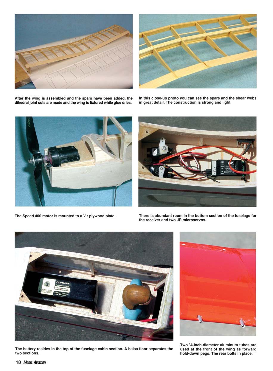
I installed one of the JR micro flight packs for another small weight savings, and it has worked fine. There is plenty of thrust in those little servos for these controls. Considering how far downfield I have chased thermals with Big Punkin, I am grateful for the plentiful range that the little receiver provides.
Construction
Careful wood selection can make a substantial difference in one of these models’ weight. My Big Punkin finished out at 17 ounces, and there is no heavy balsa in it. Most of the wood averages 6–8 pounds per cubic foot in density. Although I have to drive a considerable distance to a hobby shop that stocks balsa, I enjoy going through the selection and choosing the best pieces for the various jobs. I prefer the stiff C-grain wood for the wing ribs, and I watch for nice, stiff material from which to cut the spars. I purchase the wood in sheet form and slice off the strips as needed. If you do not have access to a good local wood supply, I have had success with Superior Balsa material, and Lone Star Balsa has a great reputation. I am going to assume that this is not your first scratch-building project and that you will understand what tools to use and where.
Build the wings first; you will need them when you are working on the fuselage. My method for cutting ribs is to trim out a pair of 1/16-inch plywood templates and make a "sandwich" with the balsa rib blanks. While clamped, sand the balsa ribs to the finished shape and cut the notches. Strip out the spars and trailing edges (TEs), and trim the angle into the TEs.
Pin the TE strip to the board (notice the shims to tilt it), and then use the ribs as spacers to locate and pin the leading edge (LE). Glue the ribs in place. When they're dry, cut through the LE and TE where shown, and trim the ends to match the dihedral. Using props to hold the panels at the correct angle for the dihedral, glue the outer panels to the center. Add the top spars.
When all of that is dry, lift it off the board and glue in the filler strips between the spars where shown. Now you can glue the bottom spar in place. At this time, trim the LE to the proper cross-section and sand away any glue bumps, etc. You can add the tips now, along with the little plywood reinforcements for the hold-down screws. Do all of this again, and you have a nice pair of wings!
Fuselage
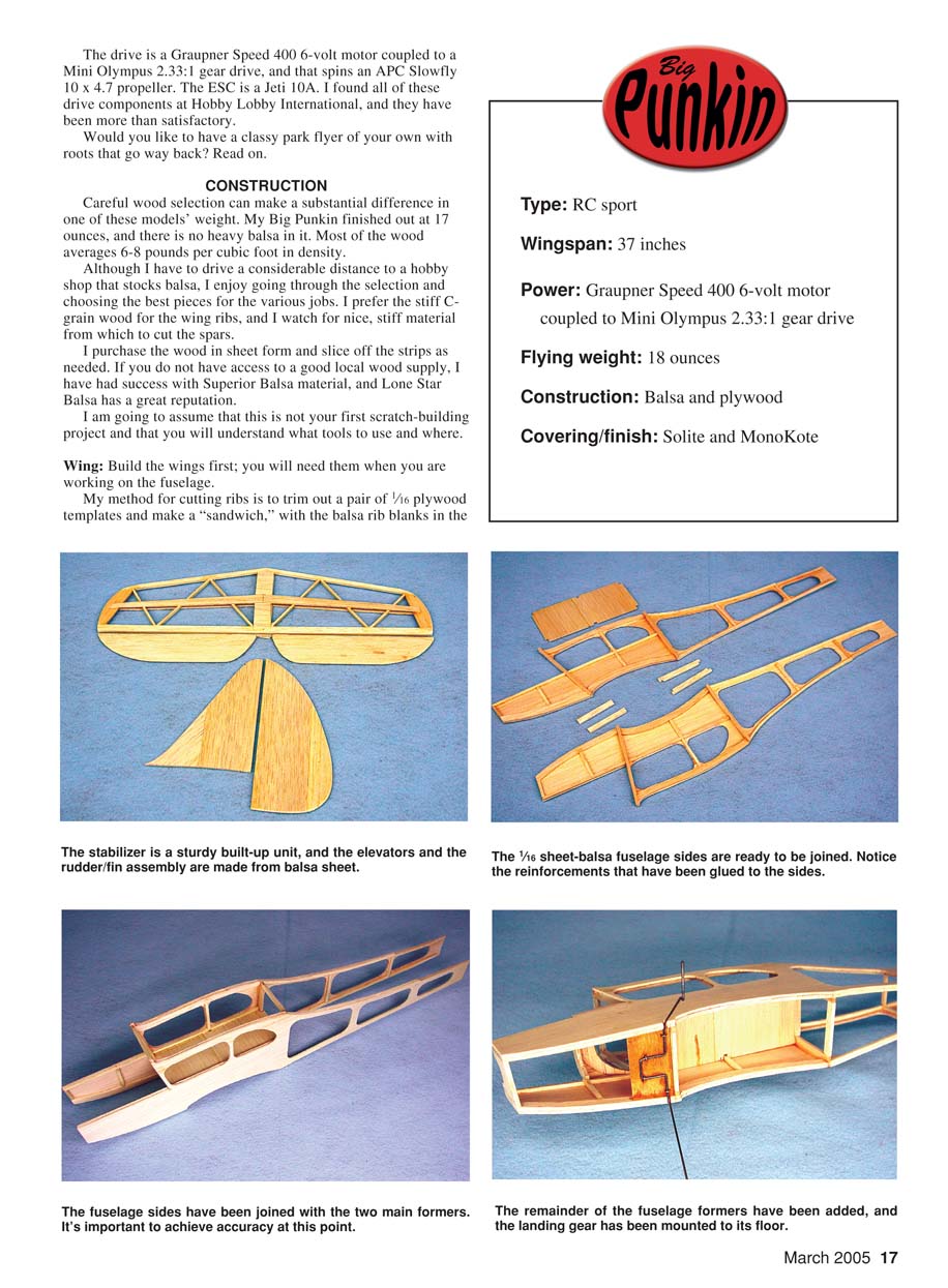
Begin the fuselage by splicing two sheets of 1/16-inch balsa to the width necessary for the fuselage sides. Cut the pieces to the outline shown on the plans, leaving the various openings solid for now.
Pinning the sides to a flat surface, glue all of the 1/8-inch balsa bracing in place where shown. Instead of bulkheads in the cabin, use strips of 1/8 x 3/8-inch balsa glued on edge in the front and back of the wings. With all of the bracing in place, cut the various openings in the sheet sides.
Join the sides at the cabin, using strips of 7/8 x 1/2-inch balsa as crosspieces. The tail may be pulled together now and glued; watch that you avoid building a banana! I had to cut partway through the bracing on the sides to pull the nose together and keep the sides straight. Add the rear cross bracing and the plywood parts for mounting the wings.
This is where those wings come in handy. Holding a wing in place, drill through the fuselage and wing for the front tubes and then the rear screws. Be sure to use the tap-size drill for the rear screws to avoid a mess later. Open up the holes in the wings for clearance at the screw locations, and tap the plates in the fuselage 6-32 for the hold-down screws. I found my plastic screws in an assortment sold at RadioShack.
Landing Gear
I use soft copper wire to lace the 1/16-inch-diameter-wire landing gear to the plywood plate, and then I flow a bit of cyanoacrylate glue over the lacing. Mine holds fine.
Glue the assembly in the location shown, placing it high enough to clear the bottom planking. Cover the front bottom with 1/16-inch balsa with the grain running across the fuselage. The top bulkheads and sheeting can go in next.
Cowl Block
I made the top cowl from a block of balsa and hollowed it, but bulkheads and sheet will work too. Fit the front block and sand the nose smooth.
I fashioned the motor mount from a piece of 1/16-inch plywood supported with a piece of 1/4-inch balsa on each side. This is a good time to fit the motor assembly and trim the necessary clearances in the front block. Set the motor aside for now, along with the fuselage.
Empennage
To get a stiff, light stabilizer, I assembled it from a 1/8-inch balsa core and added 1/16-inch sheet on the top and bottom as shown. When it was dry, I sanded the center sheeting to the wedge shape and rounded the front and tip edges. I left the TE square.
I cut the elevators from a sheet of 1/8-inch balsa. I installed the wire joiner before I cut the top apart. I also sanded the taper into the elevators while they were joined. I cut the center apart, sanded a sharp edge bevel on the front edge, and then set it aside. Cut the fin and rudder from 3/32-inch balsa sheet. You may have to do some splicing to get the width shown.
Covering
Chances are that you can do a neater job than I did, so my main suggestion is to carefully read and follow the instructions that come with the material of your choice. Avoid using MonoKote or other thick material on the wings and stabilizer that would add unnecessary weight and risk warps.
Make sure the covering is firmly attached to the rib bottoms to follow the contours of the airfoil. I found one of the little trim sealing irons handy for this. It let me bond the ribs without shrinking the covering away from them.
The windows on the fuselage sides are scraps of clear MonoKote ironed in place. The windshield came from one of those clear document protectors.
Final Assembly
I used full-span strips of clear packing tape (Scotch brand) to hinge the elevators and rudder. I left a gap of approximately 1/16 inch in the hinge line. This worked out extremely well. The hinges are free and smooth, and there is no leakage along the hinge line.
I mounted the wings to serve as a reference while I installed the tail. My system is to set the model flat on a countertop or other large, flat surface and level the wings. Then I trim the stabilizer cutout until it is level and glue it on with the wing level. This keeps the stab straight to the fuselage.
Glue on the vertical tail next. Sight it carefully to avoid any tilting. I put a short piece of packing tape between the fuselage and the rudder as a bottom stop. Glue the hinge area with thin CA. The rudder also gets a small tab glued into the bottom of the fuselage to keep it from moving in flight. Glue on the control horns.
I installed the motor unit next, and I used strips of clear tape to attach the front nosepiece. The cowl block has a strip of tape on each side, with one side folded under to form a tab. This gave me a handy location for my battery connector, for charging, etc. I used hook-and-loop material to install the battery, with the grabby loops in the airplane.
Install the receiver and servos on the bottom of the equipment plate. Servo mounting tape worked fine for me. I made my pushrods from 3/16-inch square balsa sticks, with 1/32-inch-diameter-wire ends. Rather than have adjusters, I made the last wire/stick joint with the servo in neutral and the control aligned.
The wheels are the light foam type, held on with plastic push-on keepers. I cut the tail skid from 3/32-inch plywood and painted it to match the fuselage. Being the independent type, I made my spinner from balsa and covered it with fiberglass cloth and cyanoacrylate glue.
A commercial 1.5-inch-diameter spinner would do fine. I ended up settling on an APC 10 x 4.7 propeller for my Big Punkin, but you might want to try a few sizes to get the best match.
With all but the top wing assembled, put the battery in place and then mount the wing. Check the balance, and move the battery as necessary to get the correct balance. Perform a good range check on the radio, and run up the motor to ensure that it does not interfere with the controls when the signal is weak.
Flying
Flying the Big Punkin is simple. I have never hand-launched mine, but there is plenty of power if that is necessary. The ground handling on takeoffs is normal.
On grass, hold full up until the speed builds a bit, and then go to neutral. A small tug of up will lift it right off. On pavement, it is only necessary to steer with the rudder for a few feet until there is adequate airflow over the fin.
Climb up to 100 feet or so and feel out the low-speed handling. Mine will reach full up-elevator without dropping a wing if I leave the power low and do not make large movements with the rudder. Holding full up and pushing the rudder full over should result in a spin entry. The spins are pretty, and the recovery is immediate when you neutralize the controls.
From this point on, see how much fun you can have with your Big Punkin. Let me know how you make out, and I always enjoy pictures. Happy landings.
MA Dave Robelen Route 4 Box 369 Farmville, VA 23901 [email protected]
Specifications
- Type: RC sport
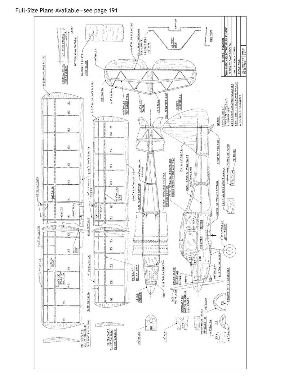
- Wingspan: 37 inches
- Power: Graupner Speed 400 6-volt motor coupled to Mini Olympus 2.33:1 gear drive
- Propeller: APC Slowfly 10 x 4.7 (used)
- ESC: Jeti 10A
- Flying weight: 18 ounces
- Construction: Balsa and plywood
- Covering/finish: Solite (wings & stabilizer) and MonoKote (fuselage)
Transcribed from original scans by AI. Minor OCR errors may remain.

