
Bill Hinnant's F-5
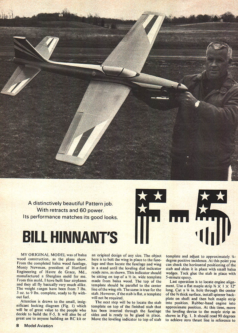
A distinctively beautiful Pattern job. With retracts and 60 power. Its performance matches its good looks.
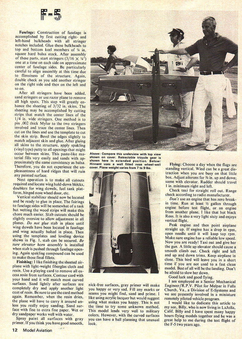
MY ORIGINAL MODEL was of balsa wood construction, as the plans show. From the completed balsa wood fuselage, Monty Newman, president of Hartford Engineering of Havre de Grace, Md., manufactured a fiberglass mold for me. From this mold, I have built four airplanes and they all fly very much alike. The weight ranges have been from 7 lbs. 3 oz. to 9 lbs. complete, ready to fly without fuel.
Leveling and Setup
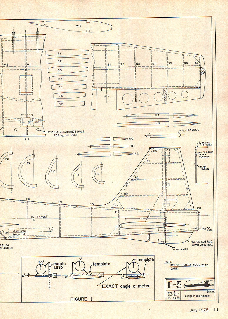
Attention is drawn to the small, insignificant looking diagram (Fig. 1) which will be of great value to the people who decide to build the F-5. It will also be of great use to anyone building an RC kit or an original design of any size. The object here is to bolt the wing in place to the fuselage and then locate the fuselage and wing in a stand until the leveling dial indicator reads zero, as shown. This indicator should be sitting on top of a 1/2-in.-wide template made from balsa wood. The top of the template should be parallel to the centerline of the wing rib. The same is true for the stab. However, if the stab is flat, a template will not be required.
The next step will be to locate the stab template on top of the finished stab that has been inserted through the fuselage sides and is ready to be glued in place. Move the leveling indicator to the top of the stab template and adjust to approximately 1/4-degree positive incidence. At this point you can check the horizontal positioning of the stab and shim it in place with small balsa wedges. Tack-glue the stab in place with 5-minute epoxy.
The last operation is to locate engine alignment. Use a flat maple strip 3/8 × 1 × 12 in. long. Cut a 1/4-in. hole through the center of the 3/8-thick surface, install spinner back-plate on shaft and then bolt the maple strip into position. Rubber-band the engine into approximate position. At this time move the leveling device to the maple strip as shown in Fig. 1. It should read 90 degrees to achieve zero thrust line in reference to the wing.
Wing Construction
For the wing has been shown on plans using a build-up construction technique. If you decide this is your cup of tea, please use an Adjusto-Jig or equivalent to assure a straight and true wing assembly. Dihedral of approximately one inch under each tip has been the most successful for me. As you can observe on plans, the wheel-retract mechanism plate will be supported in the wing and those rough landings or flying from grass fields will not worry you. Ailerons are of the barn-door type. This method was chosen in order to maintain horizontal stability at very high speeds. And—guess what—it really works. You can fly the F-5 level and very low speed with approximately 10 degrees nose-up attitude. Barn-door ailerons help when working out of cross-wind landings. To me this is worth its weight in gold when shooting through four-point rolls, Cuban eights, etc.
Fuselage Construction
Construction of fuselage is accomplished by first cutting right- and left-hand bulkheads with all stringer notches included. Glue these bulkheads to top and bottom keel members of 1/4-inch square hard balsa stock. After assembly of these parts, start stringers (3/16 × 1/4 in.) one at a time on each side on approximate center of fuselage sides. Be particularly careful to align each side at this time due to flimsy structure. Double-check as you add each stringer on one side and then on the other. After all stringers have been added, sand stringers or use a razor plane to remove all high spots. This step will greatly enhance the sheeting of 3/32-in. skins. The sheeting may be accomplished by cutting strips that match the center lines of the 1/4-in.-wide stringers. One method is to pin .002-in.-thick Mylar to the two stringers involved and trace the center lines. Then cut on the lines and use the template to cut the skin strip. Bevel the edges slightly to match adjacent skin and glue. After gluing all skins wing. Double check all surfaces and if readings maintain the same as previously described, drill engine mounting holes. This method will take the guesswork out of locating the stab in relation to the wing and the engine positioning. I have found, due to the curvature of the fuselage, that it is easy to be fooled in this final positioning and, after final building, it is a heartbreak to learn you have made a mistake.
Before starting fabrication of this model, I would suggest that details like motor mounts (3/8" plywood), firewall bulkhead (3/8" plywood), main landing gear platforms (3/16" plywood) should be fabricated first. These items will help your learning curve on the plans and will insure proper cut outs for these details as your building progresses. I would also recommend using epoxy for holding heavily loaded items, like motor mounts to firewall, etc. and water base glues for internal structures.
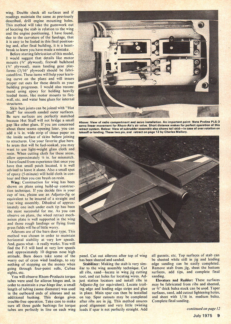
Skin butt joints can be joined with "Hot Stuff" for smooth sanded outer surfaces. Be sure surfaces are perfectly matched because Hot Stuff will not bridge a small gap like other glues. If you are concerned about these seams opening later, you can add a 1/4-in. wide strip of tissue paper on the inside surface of skins before joining to structures. Use your favorite glue here. In areas that will be fuel-soaked, you may elect to use light-weight glass cloth and resin. When cutting cloth for these areas, allow approximately 1/4 in. for mismatch. I have found from experience that once you have the small patch located, it is well advised to leave it alone. Also a small spot of epoxy (5-minute) will hold cloth in contour and then you can brush on resin.
Wing
Construction for wing has been shown on plans using build-up construction technique. If you decide this is your cup of tea, please use an Adjusto-Jig or equivalent to be insured of a straight and true wing assembly. Dihedral of approximately one inch under each tip has been the most successful for me. As you can observe on plans, the wheel retract mechanism plate is well supported in the wing and those rough landings or flying from grass fields will be of little worry.
Ailerons are of the barn-door type. This method was chosen in order to maintain horizontal stability at very low speeds. And, guess what—it really works. You will find the F-5 will land at very low speeds and approximately 10 degrees nose high attitude. Barn doors take some of the worry out of cross wind landings, to say nothing of stopping on the money when going through four-point rolls, Cuban eights, etc.
You will observe Rohm-Products torque tubes were used for aileron hinges and, in order to maintain a true hinge line, a small length of tubing (same diameter) was used in the outboard ends of ailerons and an additional bushing. This design gives trouble-free operation. Take care to make sure all three guide bushings for torque tubes are perfectly in line on each wing panel. Cut out ailerons after top of wing has been sheeted and sanded.
Stabilizer
Making the stab is very similar to the wing assembly technique. Cut all ribs, sand, locate in wing jig cutting tool, and cut holes for locating wires. Adjusto-Jig (or equivalent). Locate trailing edge and leading edge strips and glue in place. Main spar can then be installed on top. Spar cutouts may be completed after ribs are in jig. This method assures good alignment and very little twisting loads if spar is not perfectly straight. Add all gussets, etc. Top surfaces of stab can be sheeted while still in jig and leading edge sanding can be easily completed. Remove stab from jig, sheet the bottom surfaces, add tips, and complete final sanding.
Elevators and Rudder
These surfaces may be fabricated from ribs and sheeted, or 3/8" thick balsa stock can be used. Tapered surfaces, sand, and cut out lightening holes, and sheet with 1/16 in. medium balsa. Complete final sanding.
continued on page 12 W1 W2 W3 W4 W5 W6 W7 W8 W9 W10 W11
F1 F2 F3 F4 F5 F6 F7
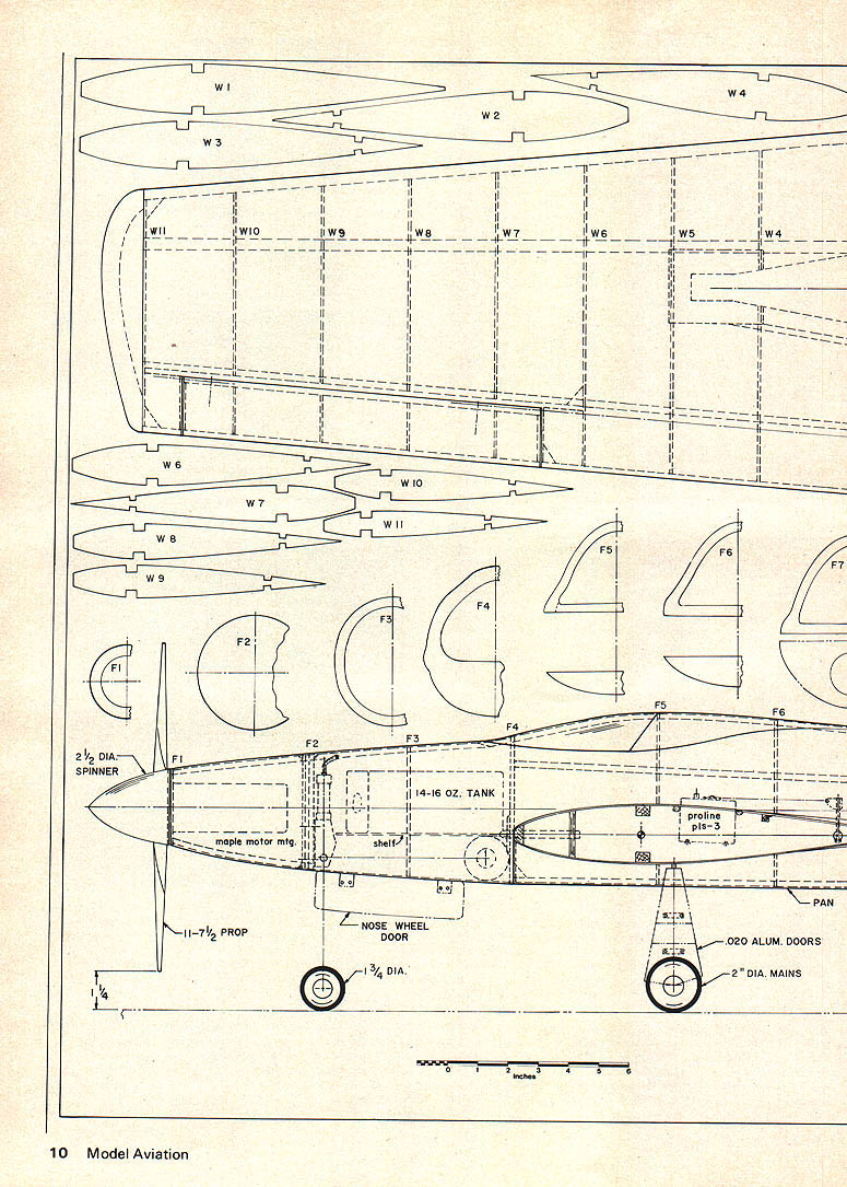
2½ DIA. SPINNER
11-7½ PROP
maple motor mtg.
14-16 OZ. TANK
shelf
NOSE WHEEL DOOR
1¾ DIA.
proline pls-3
PAN
.020 ALUM. DOORS
2" DIA. MAINS
10 Model Aviation
Leveling and Setup
The last operation is to locate engine alignment. Use a flat maple strip 3/8 × 1 × 12 in. long. Cut a 1/4-in. hole through the center of the 3/8-thick surface, install spinner back plate on shaft and then bolt the maple strip into position. Rubber-band the engine into approximate position. At this time move the leveling device to the maple strip as shown in Fig. 1. It should read 90 degrees to achieve a zero thrust line in reference to the wing.
Wing Construction
The wing has been shown on plans using a build-up construction technique. If you decide this is your cup of tea, please use an Adjusto-Jig or equivalent to assure a straight and true wing assembly. Dihedral of approximately one inch under each tip has been the most successful for me. As you can observe on plans, the wheel-retract mechanism plate will be supported in the wing and those rough landings or flying from grass fields will not worry you.
Ailerons are of the barn-door type. This method was chosen in order to maintain horizontal stability at very high speeds. And—guess what—it really works. You can fly the F-5 level and very low speed with approximately 10 degrees nose-up attitude. Barn-door ailerons help when working out of cross-wind landings. To me this is worth its weight in gold when shooting through four-point rolls, Cuban eights, etc.
Fuselage Construction
Construction of fuselage is accomplished by first cutting right- and left-hand bulkheads with all stringer notches included. Glue these bulkheads to top and bottom keel members of 1/4-inch square hard balsa stock. After assembly of these parts, start stringers (3/16 × 1/4 in.) one at a time on each side on approximate center of fuselage sides. Be particularly careful to align each side at this time due to flimsy structure. Double-check as you add each stringer on one side and then on the other.
After all stringers have been added, sand stringers or use a razor plane to remove all high spots. This step will greatly enhance the sheeting of 3/32-in. skins. The sheeting may be accomplished by cutting strips that match the center lines of the 1/4-in.-wide stringers. One method is to pin .002-in.-thick Mylar to the two stringers involved and trace the center lines. Then cut on the lines and use the template to cut the skin strip. Bevel the edges slightly to match adjacent skin and glue. After gluing all skins. to the structure, apply spackling (vinyl type) putty to all openings that might occur between skins. This paste-like material fills very easily and sands with approximately the same consistency as balsa. Therefore, you do not experience the unpleasantness of hard ridges that will ruin any painted surface.
Next operation is to make all cutouts required and locate wing hold-down blocks, doublers for wing dowels, fuel tank platform, hinged nose wheel door, etc.
Vertical stabilizer should now be located and be ready to glue in place. The fairings to fuselage sides will be somewhat of a task but wetting the wood strips will make this chore much easier. Stab cutouts should be slightly oversize to allow adjustment in all planes. Do not glue stab in place until wing dowels have been located in fuselage and wing actually bolted in place. Then using the templates and leveling device shown in Fig. 1, stab can be secured. Be sure elevator horn assembly is installed when stab is pushed through fuselage opening. Again spackling compound can be used to make those final fillets.
Finishing:
I like finishing the sheeted airplane with light-weight fiberglass cloth and resin. Use a playing card to remove all excess resin from surfaces. Contour card with your hand and it will match most curved surfaces. Sand lightly after surfaces are completely dry and apply another light coat of resin. Be sure to use the card method again. Remember, when the resin dries, the plane will have to carry it around unless you really enjoy sanding. Sand surfaces with fine to extra fine paper. Wet or dry sandpaper works well with water.
Spray paint all surfaces with gray primer. If you think you have good smooth, nick-free surfaces, gray primer will make you happy or very sad. Fill any marks or seams you might find, sand and prime. I like using acrylic lacquer but would suggest using what makes you happy. This is not the time to try some unknown method. This model lends very well to military colors. However, with the curved surfaces you can have a ball planning that unusual look.
Flying:
Choose a day when the flags are standing vertical. Wind can be a great distraction when you are busy on that little box. Adjust ailerons for 3/8 in. up and down; same with elevator. Rudder should travel 1 in. minimum right and left.
Check taxi for straight roll out. Range check according to radio manufacturer. Don't use an engine that has zero break-in time. Run at least 1/2 gallon through engine before test flight, or an engine from another plane. I like the hot black Ross. It is also a very light sixty and enjoys vertical flight.
Peak engine and then point airplane straight up. If engine has a drop in rpm, open needle until it will keep top rpm. Make sure engine has a reliable low speed. Now you are ready! Taxi out and give her the gun. A little up elevator should cause a smooth climb out. Check right and left and up and down trims. Keep airplane in close. This bird will leave you in a short time if you are not used to a fast clean model. Best of all will be the landing. Don't be afraid to slow her down.
Good luck and good flying.
I am employed as a Senior Mechanical Engineer/R.P.V. Pilot for Melpar in Falls Church, Va., a Division of E-Systems who are presently involved in a miniature remotely piloted vehicle program.
I would like to dedicate this article to my son, Billy, who is now living in La Jolla, Calif. Billy and I have spent many happy hours flying models together and he was a great help to me during the test flight of the F-5 two years ago.
Transcribed from original scans by AI. Minor OCR errors may remain.

