
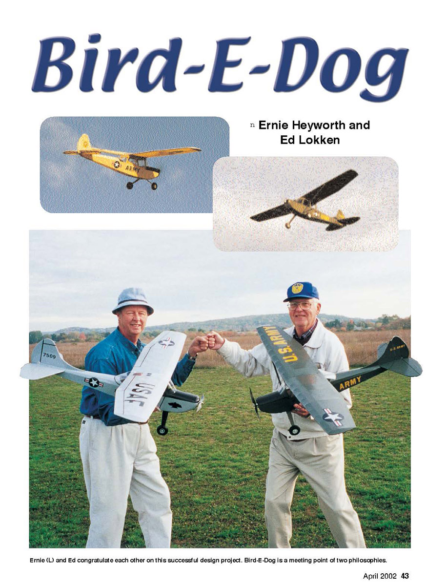
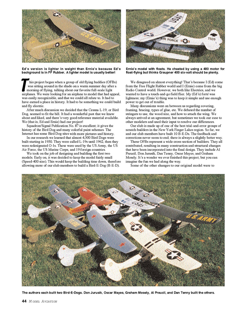
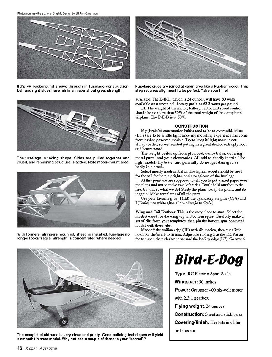
Bird-E-Dog
Ernie Heyworth and Ed Lokken
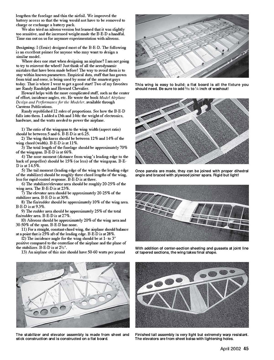
Ernie (L) and Ed congratulate each other on this successful design project. Bird-E-Dog is a meeting point of two philosophies. This project began when a group of old flying buddies (OFBs) was sitting around in the shade on a warm summer day after a morning of flying, talking about our favorite full-scale light airplanes. We were looking for an airplane to model that had appeal, was easily recognizable, and that we could all relate to. It had to have earned a place in history. It had to be something we could build and fly electric.
After much discussion we decided that the Cessna L-19, or Bird Dog, seemed to fit the bill. It had a wonderful past that we knew about and liked, and there's very good reference material available. We (that is, Ed and Ernie) had our project!
Squadron/Signal Publication No. 87 is excellent; it gives the history of the Bird Dog and many colorful paint schemes. The Internet has some Bird Dog sites with more pictures and history.
In our research we learned that almost 4,300 Bird Dogs were built starting in 1950. They were called L-19s until 1962, then they were redesignated O-1s. These were used by the US Army, the US Air Force, the US Marine Corps, and 19 foreign countries.
We took on the job of designing and building the first two models. Early on, it was decided to keep the model fairly small (Speed-400 size). This would keep the building time down, therefore allowing more of our club members to build a Bird-E-Dog (B-E-D).
We disagreed on almost everything! That's because I (Ed) come from the Free Flight Rubber world and I (Ernie) come from the big Radio Control world. However, we both like Electrics, and we wanted to have a touch-and-go field flier. My (Ed's) forte was lightness; my (Ernie's) thing was to keep it simple and use enough power to get out of trouble.
Many discussions went on between us regarding covering, framing, bracing, types of glue, etc. We debated the number of stringers to use, the wood size, and how to attach the wing. We always arrived at an agreement, but sometimes we took our case to other modelers and used their input to resolve our differences.
Our club is made up of one of the best trial-and-error groups of scratch-builders in the New York Finger Lakes region. So far, we and our club members have built 10 B-E-Ds. The feedback and corrections never seem to end; there is always a slightly better way.
These OFBs represent a wide cross-section of builders. They all contributed, resulting in many construction and structural changes that have been incorporated into the final design. They include Al Preucil, Don Jurusik, Dan Tenny, Oscar Mayes, and Graham Mosely. It's a wonder we ever finished this project, but you can imagine the fun we had along the way.
Some of the other changes to our original model were lengthen the fuselage and thin the airfoil. We improved the battery access so that the wing would not have to be removed to charge or exchange a battery pack.
We also tried an aileron version but learned that it was slightly too sensitive, and the increased weight made the B-E-D a handful. Time ran out on us for any more experimentation with ailerons.
Designing: I (Ernie) designed most of the B-E-D. The following is an excellent primer for anyone who may want to design a similar model.
Where does one start when designing an airplane? I am not going to try to reinvent the wheel! Just think of all the aerodynamic mistakes that have been made before! The way to avoid them is to stay within known parameters. Empirical data, stuff that has grown from trial and error, is being used by some of the smartest guys today. That is where I went to get a good start! Two of my favorites are Randy Randolph and Howard Chevalier.
Howard helps with the more complicated stuff, such as the center of effort, incidence angles, etc. He wrote the book Model Airplane Design and Performance for the Modeler, available through Carstens Publications.
Randy republished 12 rules of proportions. See how the B-E-D falls into them. I added a 13th and 14th: the weight of electronics, hardware, and the watts needed to power the airplane.
1) The ratio of the wingspan to the wing width (aspect ratio) should be between 5 and 6. B-E-D is at 6.25.
2) The wing thickness should be between 12% and 14% of the wing chord (width). B-E-D is at 11%.
3) The total length of the fuselage should be approximately 70% of the wingspan. B-E-D is at 66%.
4) The nose moment (distance from wing's leading edge to the back of propeller) should be 15% (or less) of the wingspan. B-E-D is at 14.5%.
5) The tail moment (leading edge of the wing to the leading edge of the stabilizer) should be roughly three chord lengths of the wing, less for rapid control response. B-E-D is at three.
6) The stabilizer/elevator area should be roughly 20-25% of the wing area. The B-E-D is at 23%.
7) The elevator area should be approximately 20-25% of the stabilizer area. B-E-D is at 30%.
8) The fin/rudder should be approximately 10% of the wing area. B-E-D is at 9.3%.
9) The rudder area should be approximately 25% of the total fin/rudder area. B-E-D is at 27%.
10) Ailerons should be approximately 20% of the wing area and 30-50% of the span. B-E-D has none.
11) For a straight, constant-chord wing, the airplane should balance at a point that is 25% aft of the leading edge. B-E-D is at 28%.
12) The incidence angle for the wing should be at 1- to 3-positive compared to the centerline of the airplane and the plane of the stabilizer. B-E-D is at 2½°.
13) An airplane of this size should have 50-60 watts per pound
CONSTRUCTION
My (Ernie's) construction habits tend to be to overbuild. Mine (Ed's) are to be a little light since my modeling experience has come from rubber-powered models. Try to keep it light; more is not always better, so we resisted putting in a great deal of extra plywood and heavy wood.
The weight builds up from plywood, dense balsa, covering, metal parts, and your electronics. All add to deadly inertia. The light models fly better and generally do not get damaged as badly in a crash.
Select mostly medium balsa. The lighter wood should be used for the tail feathers, uprights, and crosspieces of the fuselage.
At this point we're supposed to tell you to put waxed paper over the plans and not to make two left sides. Don't hold our feet to the fire, but this is what we do! Study the plans, study the parts, and do it again! Make templates of all the parts.
Use your favorite glue; I (Ed) use cyanoacrylate glue (CyA) and I (Ernie) use white glue. (I am allergic to CyA.)
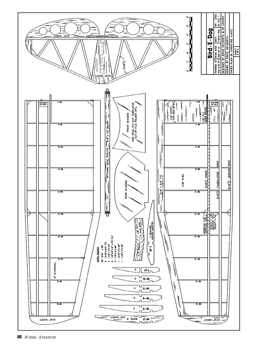
Wing and Tail Feathers: This is the easy place to start. Select the hardest wood for the wing top and bottom spars. Carefully make a set of ribs from your templates, then pin the bottom spar down and load it with these ribs.
Mark off the trailing edge (TE) with rib spacing, then cut a little notch for the 1/8 rib to fit into. Adjust the rib length at the TE. Put on the top spar, the turbulator spar, and the leading edge (LE). Go over all your glue joints with white glue. Add the gussets, center shear webbing, and wingtips.
When joining the wing halves with the 1/8 plywood dihedral center brace, don't build in a propellerlike warp. Set a level spacer four inches high under one half of the wing and make sure the other half is flat and pinned down.
Be fairly liberal with glue at the centersection. Glue in the balsa block where the front hold-down bolt goes through the wing. Sheet the center-section with 1/16 sheet balsa. (I (Ernie) use a continuous piece without a center break by using small weights and fast glue. I (Ed) use separate pieces. Either way works fine.)
After the center-section is sheeted, use fiberglass cloth top and bottom of the center seam. It will help prevent the wing bolts from cutting into the sheeting.
The vertical and horizontal stabilizers are straightforward. The lightening holes aren't necessary, but they are fun if you have Forstner bits and a drill press.
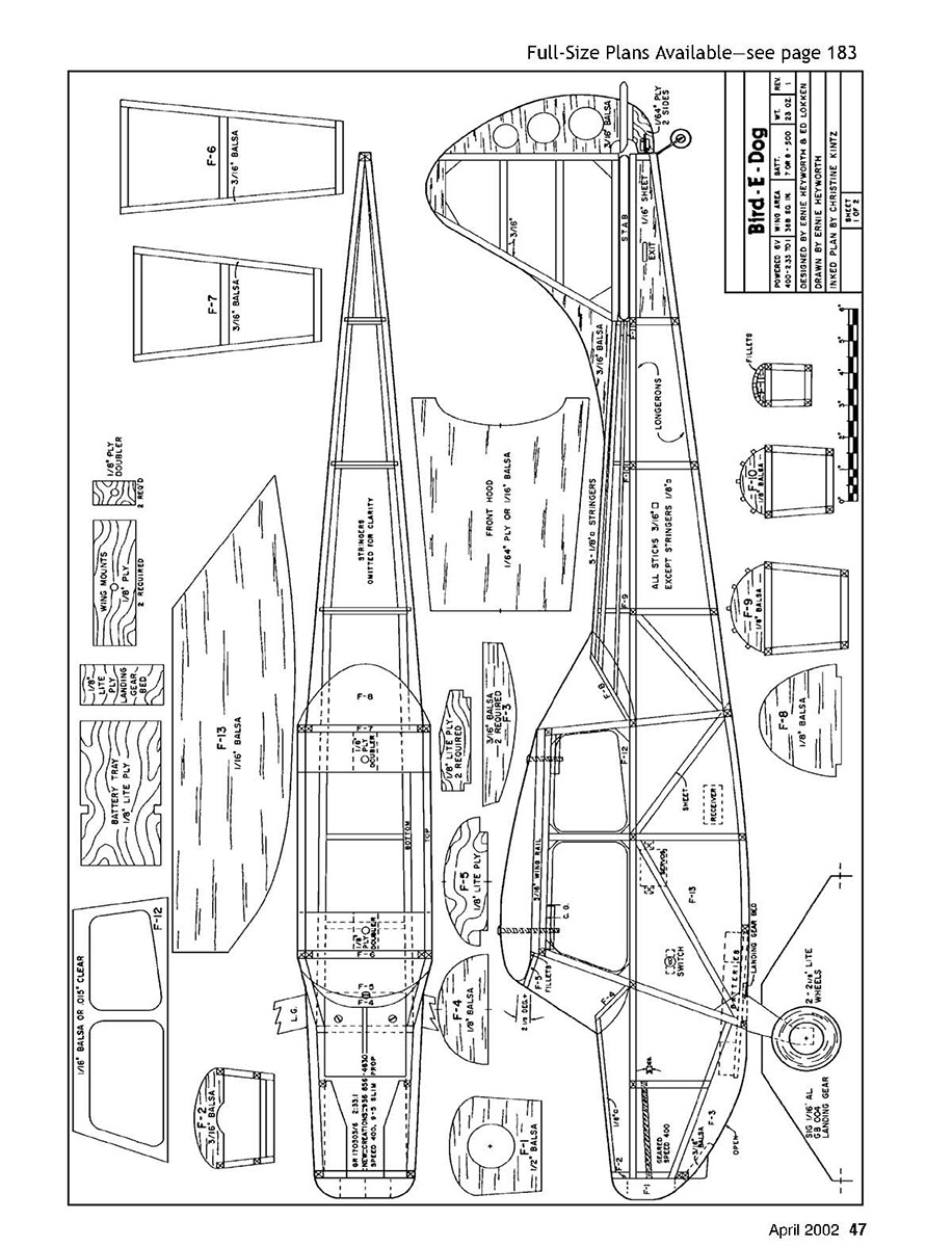
Fuselage: Select medium-weight 3/16 square balsa sticks for the two longerons for each fuselage side and lighter sticks for the uprights and crosspieces. Add the 3/16 sheet F3 near the front of the fuselage. Do not add the 3/16 top square wing rails at this time.
After each side is completed, add the 1/16 sheet pushrod filler pieces that are located under the stabilizer. Use caution here so you make a right- and left-side fuselage, as the pushrod filler sheet is flush with the outside of the fuselage.
After you have made the two fuselage sides, make the cabin formers F6 and F7. Glue these formers to one side of the fuselage at 90° to the fuselage side. Put the other fuselage side in place. When you are satisfied that the sides are square and true to each other, glue the second side to F6 and F7.
Glue the Lite Ply landing-gear plate and the two wing hold-down plates. Don't forget to add the additional Lite Ply pieces to the wing hold-down plates where the bolts are used to hold the wing on. You will drill and tap for the wing hold-down bolts later.
When the glue has dried, glue in the bottom crosspieces between F6 and F7. Slightly taper the tail post of the fuselage, then squeeze together and glue.
Cut and glue in the remaining crosspieces from F7 to F11. Use the various cross-sections for the proper length of the upper and lower crosspieces. (The bottom crosspieces are shorter than the top. This gives the B-E-D fuselage its distinctive look.) Make formers F2, F4, F8, F9, F10, and F11 at this time.
Lightly glue in former F8. You will have to bevel it for a proper fit at the approximate angle shown on the plans. Glue formers F9, F10, and F11 in place. Add the 1/8 square top stringers.
The angle of F8 may have to be adjusted so that the stringers make proper contact. When you are satisfied with the angle, permanently glue F8 in place. After all the stringers are in place, fill the gap between the stringers at F11 with scrap balsa and sand to shape.
Mark each side of the fuselage for the location of the motor mounts. We have learned that roughly 3° downthrust works the best. Make the two motor mounts and glue in place. Test-fit the motor and gearbox; some trimming may be required.
Make the battery box from 1/8 Lite Ply, and carefully install it in the location shown on the plans.
Add former F2. Glue former F4 at the angle shown on the plans. Cut from 1/16 sheet F12 and F13. Test-fit to the fuselage sides. Some trimming may be required. When you are happy with the fit, glue in place.
Add the 1/8 square stringer from F2 to F4. Use the template on the plans for the hood. We have used 1/16 balsa and 1/64 plywood. Use whatever you have and are most comfortable with. Add the nose block F1 in place, and shape as shown on the plans.
Add the two 3/16 square wing rails and a slightly taper to the dihedral angle of the wing. Place the wing on the rails, and drill through the wing and the wing mounts at the two locations shown on the plans. Tap the wing mount for the hold-down bolts. Bolt the wing in place, then glue F5 in place.
Bend the landing gear as shown on the plans. We used Sig's aluminum blank #GB004. Drill the gear for at least three 3/16-inch-long screws, and attach.
Placement and Angles: Mounting the motor and placing the servos is a personal thing that has to fit you and your equipment.
We learned that at least 3° downthrust on the motor and 2 1/2° of positive wing incidence works very well. This has worked out as an average on the 10 airplanes that have been built. The measuring setup is with the stabilizer level, the wing bolted on, and using an incidence meter.
Covering: With all the B-E-Ds we have built, you can probably imagine that an array of coverings and colors have been used. We have used MonoKote®, Litespan, and UltraCote®. All worked very well. Use the type of covering you are comfortable with.
After covering the stabilizer, fin, elevator, and rudder, use your favorite hinge material. (I (Ernie) used a clear tape and I (Ed) used Sig's Easy Hinges.) Attach the control horns to the elevator and rudder, then attach to the fuselage.
You can find decals such as Stars and Bars in Sig's catalog. Lettering, in a contrasting color, can be cut from the same material with which you covered the model.
Make a template of the front and rear windows from lightweight construction paper or manila-folder stock. Test-fit the templates, and trim until you are satisfied with the fit.
Make all the windows from .015 clear PETG (Polyethylene Terephthalate Glycol modified), which you can find at most hobby shops. Attach the windows with Super R/C 56 glue.
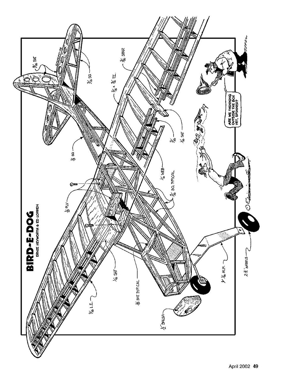
Install the servos and pushrods. Wing struts can be added now. They are not functional, but they add to the overall look of the B-E-D. Adjust the length of the struts to fit from the bottom of the fuselage to the gusset in the wing.
Equipment: For a simple radio we chose the Hitec Focus III SS AM with two HS-81 servos. Although inexpensive, this is all the airplane needs.
The speed controllers we have used are Castle Creations' Sprite-25 and Pixie-14 and New Creations R/C's NCM20, but any 15- to 25-amp controller would work fine.
The motor is a Graupner 400 six-volt with a Graupner 2.3:1 gearbox. We have used APC Electric and Graupner slips 9 x 5 and 9 x 6 propellers.
For batteries use a seven- or eight-cell pack of 500, 600, or 700 mAh. The eight cells will ROG (rise-off-ground) the B-E-D with ease; the 700 mAh provide long-lasting flights.
Balance and Setup: Set the center of gravity (CG) in front of the main spar for average flying. We use Velcro™ on the battery tray and some on the battery, then we adjust the battery location for the desired CG location.
If you are a hotshot and like spins and snaps, you can push it behind the main spar. Throws of 3/8 inch up and down and 5/16 inch left and right are roughly average. More throw gives you a snappy airplane, and less gives you a smoother-flying model.
Add 3/16 inch of washout to the tips (raise TE 3/16). This makes the airplane more docile and less prone to tip-stall.
Flying: What if we said it looks pretty in the air and is just pleasant to fly? Or we could go for the buzzwords and describe it as a comfortable sport airplane.
To say this model might be boring for a Pylon or Pattern flier would be honest. To say it will do a lazy flat figure eight within the flying-field boundaries would also be honest.
My (Ernie's) thing is low and slow or touch-and-go, or standing still in the wind. After all, it is a Bird-E-Dog. Have you ever gone on a dawn patrol for a woodchuck?
Keep it light! Don't make a fancy Scale project out of it. Make it your everyday, relaxing flier! Let the stressed-out people at the field have a turn! Bring only three battery packs, a transmitter, and the airplane to the field. Don't wire it in, tweak it, or lug a heavy field box to the field. Just play show-off and have fun!
Let us know how your Bird-E-Dogs fly. MA Ernie Heyworth 109 Hidden Ln. Horseheads NY 14845 [email protected]
Ed Lokken 165 Overlook Dr. Horseheads NY 14845 [email protected]
Bird-E-Dog
Type: RC Electric Sport Scale
Wingspan: 50 inches
Power: Graupner 400 six-volt motor with 2.3:1 gearbox
Flying weight: 24 ounces
Construction: Sheet and stick balsa
Covering/finish: Heat-shrink film or Litespan No running article text appears on this scanned page — it contains the full-size plans and part diagrams for "Bird-E-Dog" (plans sheet only). There is no continued narrative or instructional text to extract. No continued article text appears on this scanned page — it contains the full-size plans and part diagrams for "Bird-E-Dog" (plans sheet only). There is no narrative or instructional text to extract. No continued article text appears on this scanned page — it contains the full-size plans and part diagrams for "Bird-E-Dog" (plans sheet only).
Transcribed from original scans by AI. Minor OCR errors may remain.

