
Borealis
by Ben Lanterman
Build your own RC bat in time for Halloween
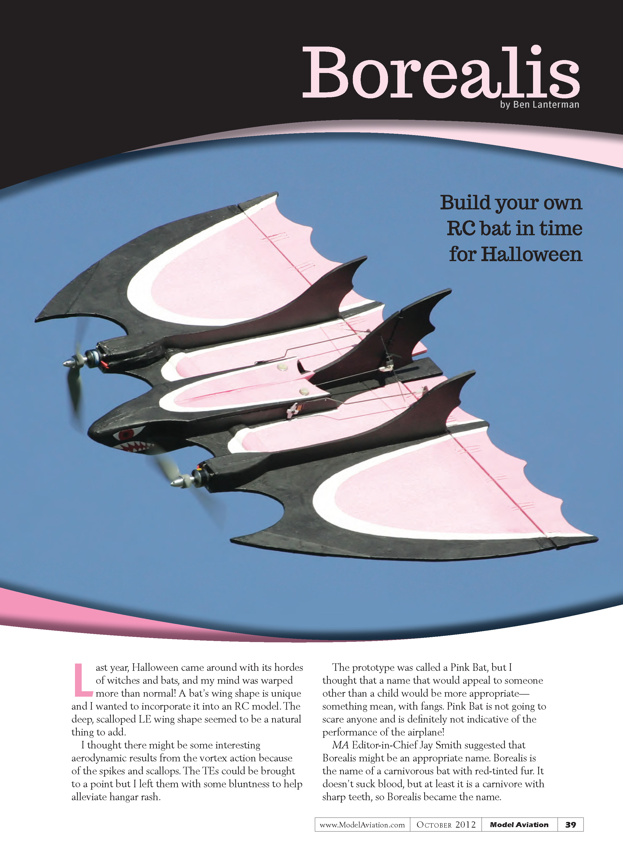
Last year, Halloween came around with its hordes of witches and bats, and my mind was warped more than normal! A bat’s wing shape is unique and I wanted to incorporate it into an RC model. The deep, scalloped leading-edge wing shape seemed a natural thing to add.
I thought there might be some interesting aerodynamic results from the vortex action because of the spikes and scallops. The trailing edges could be brought to a point but I left them with some bluntness to help alleviate hangar rash.
The prototype was called a Pink Bat, but I thought that a name that would appeal to someone other than a child would be more appropriate—something mean, with fangs. Pink Bat is not going to scare anyone and is definitely not indicative of the performance of the airplane! MA Editor-in-Chief Jay Smith suggested that Borealis might be an appropriate name. Borealis is the name of a carnivorous bat with red-tinted fur. It doesn’t suck blood, but at least it is a carnivore with sharp teeth, so Borealis became the name.
I had a second thought about incorporating spikes into the design, but not about the aerodynamics resulting from their presence. The second thought concerned the spike’s strength. If I left the foam spike in its natural condition, it would be vulnerable to accidental bumps, hangar rash, and perhaps break on landing. However, in a year of flying the old prototype without any reinforcement, the spike only broke once. I fixed it on the field with CA. The airplane can be flown easily into a nose-high landing that prevents the spikes from contacting the ground. If I reinforced the spike too much it could be a “pointy thing” on the airplane that could potentially be dangerous. I attached a layer of fabric with CA to the top and bottom of the points, which strengthened them as I expected, but not so much that I thought they were dangerous. The spike can still break during unplanned contact with the ground or an object, but it poses a lesser danger to weak human flesh than a pointed spinner or sharp propeller, spinning or otherwise.
The basic airplane can vary. The vertical tail shapes are strictly for looks. You could have two outboard fins or one single fin. If you want to make the shapes more angular, that is fine. A canopy similar to the F-117 could be added or you could change the outer wing curve to several straight segments. I like the look of the three fins and the scalloped, curved edges. I have always been a Batman fan. The inlets on each side of the nose are functional and allow cooling air to flow over the ESCs. The ducts give an area to grip during the underhand launch. You can launch overhand by holding the battery area.
Construction
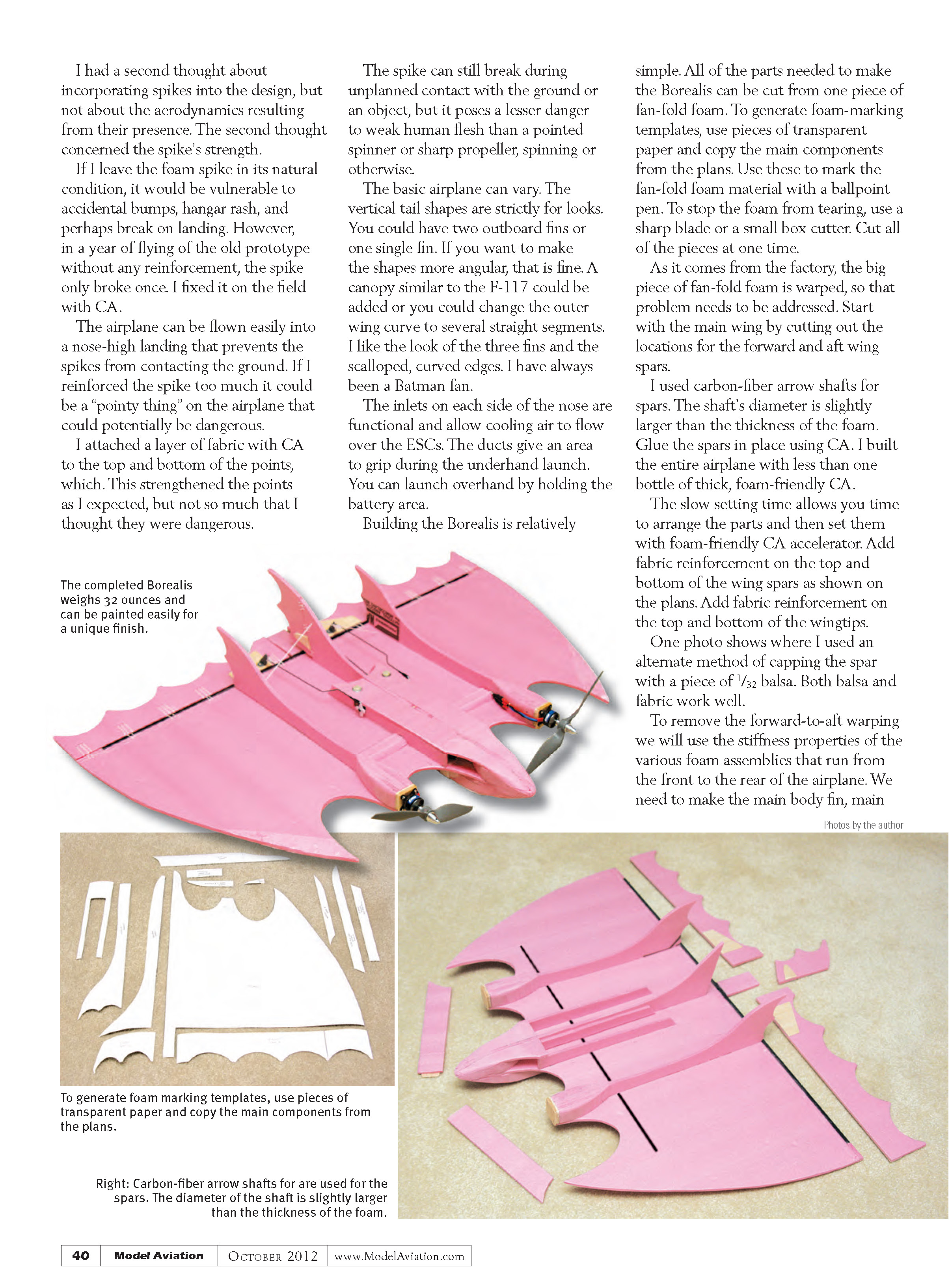
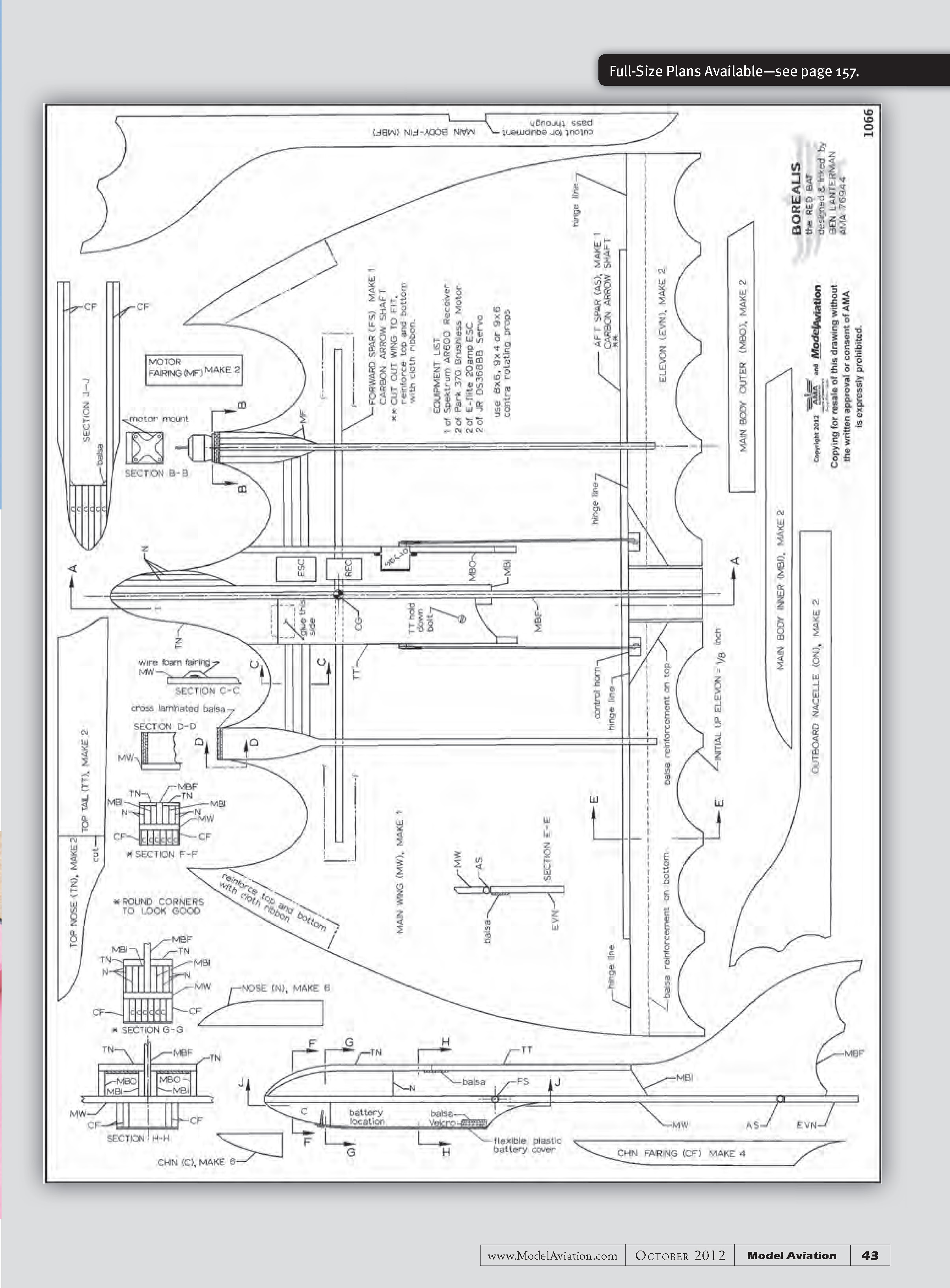
Building the Borealis is relatively simple. All of the parts needed to make the Borealis can be cut from one piece of fan-fold foam. To generate foam-marking templates, use pieces of transparent paper and copy the main components from the plans. Use these to mark the fan-fold foam material with a ballpoint pen. To stop the foam from tearing, use a sharp blade or a small box cutter. Cut all of the pieces at one time. As it comes from the factory, the big piece of fan-fold foam is warped, so that problem needs to be addressed.
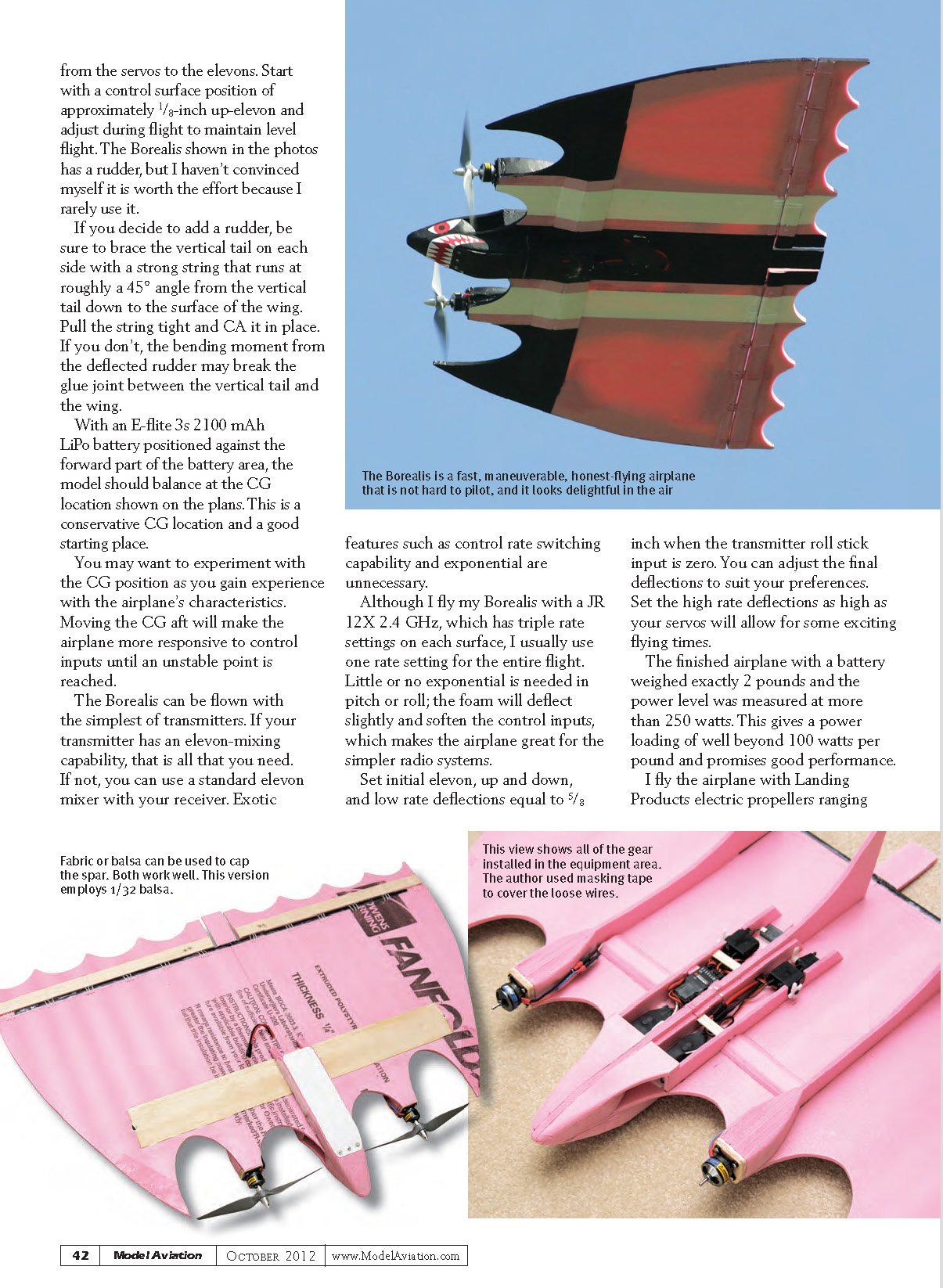
Start with the main wing by cutting out the locations for the forward and aft wing spars. I used carbon-fiber arrow shafts for spars. The shaft’s diameter is slightly larger than the thickness of the foam. Glue the spars in place using CA. I built the entire airplane with less than one bottle of thick, foam-friendly CA. The slow setting time allows you time to arrange the parts and then set them with foam-friendly CA accelerator. Add fabric reinforcement on the top and bottom of the wing spars as shown on the plans. Add fabric reinforcement on the top and bottom of the wingtips. One photo shows where I used an alternate method of capping the spar with a piece of 1/32 balsa. Both balsa and fabric work well.
To remove the forward-to-aft warping we will use the stiffness properties of the various foam assemblies that run from the front to the rear of the airplane. We need to make the main body fin, main body inboard, and nose assembly. To do this, glue one main body inboard to each side of the main body fin while bracing the vertical tail upright; hold until the glue hardens.
Add the nose assemblies to each side of the front. Cut the nose to shape as shown on the top view of the plans. Then build up two subassemblies consisting of the outboard nacelle and the motor fairing parts. To form a motor mount, add three pieces of balsa, glued in a cross-grain fashion, to the front of the outboard nacelle. Cut the motor fairings to shape as shown on the top view of the plans.
Now you can glue the above assemblies to the main wing at the locations shown on the plans. Also glue the two main body outboard pieces to the main wing. You will end up with no warps in the wing. Glue the top nose parts to the airplane. The foam bends easily around the nose and you can hold it until the accelerator sets the CA, resulting in a nice, flat-bottomed, foam assembly.
The top tail part is removable to give access to the electronics. Glue a small piece of balsa under the forward part of the top tail. This will let it slide under the top nose and lock the forward part of the top tail in place. A nylon bolt that goes through the rear of the top tail, going down to the wing, holds the top tail in place.
The battery-holder section is made from the chin parts and the chin fairing parts. Stack them as shown on the plans and add a small balsa triangle to reinforce the inside corners where the cross section is thin. Glue the completed battery holder assembly to the bottom of the wing.
Use a sharp knife and sandpaper to shape the nose as desired. I didn't round the nose much and I left the flying surfaces with square edges, although you can round them. After shaping the overall edges, cut a piece of flexible plastic (a milk jug would work nicely) and using long screws, attach it to the front of the battery holder assembly as shown on the plans.
To hold down the rear of the flexible plastic during flight, make a Velcro hold-down assembly. Glue a piece of balsa across the back of the battery holder assembly and attach a piece of loop Velcro to it. Attach the hook Velcro to the flexible plastic piece. Recess the balsa piece as shown on the plans to allow the plastic to flatten against the bottom of the battery area. Add loop Velcro to the bottom of the wing inside of the battery assembly to provide a place to anchor the flight battery (which has hook Velcro attached).
The flexible elevons need a piece of 1/16-inch hard balsa reinforcement glued spanwise across their bottom. Add some balsa on the top where the control horn attaches to stiffen the elevons.
Electronics and linkages
Place the E-flite Park 370 motors as shown on the plans. These produce much power and work well on this airplane. Park 400 powerplants would work well and provide more power.
Route the wires going to the ESC along the motor fairings and along the wing into the equipment area. I used masking tape to cover the loose wires on the motor fairings. I used a piece of hollowed-out foam to cover the loose wires on the top of the wing and painted the tape to look better.
Locate the E-flite 20-amp ESCs and receiver on the wing as shown on the plans. You can spot-glue them down or use Velcro.
I used a Spektrum AR7000 receiver, but I recommend the less-expensive Spektrum AR600. Route the wiring as needed through the cutout in the main body fin. I use the BEC receiver power output from both ESCs instead of removing one of the power leads.
Notch the main body outboard pieces to accept the servos. I added the grommets to the servos and used CA on the grommet/foam interface to hold the servo in place. The JR DS368BB servos I used may be overkill in terms of torque, but I had them available, and the metal gears won't break. Don't use micro servos in this application. I doubt that they have sufficient torque.
Finally, add some small pieces of balsa across the equipment bays to hold the wiring down. I used string hinges to attach the elevons to the wing. They have no binding issues and are easy to install. Drill holes through the wing in front of the aft spar and in each elevon. Stiffen the ends of the string with CA and thread it through the wing and elevon. Install the control horns with bolts through the elevons. Assemble and attach the pushrod assemblies to the servo arms. Close the top tail, install the battery, and balance the airplane. Add the 2-ounce nose weight as shown on the plans and check the balance at the locations shown. I found it beneficial to have the airplane balanced slightly nose-heavy.
I fly my Borealis with a Spektrum JR 12X 2.4 GHz transmitter, but the Borealis can be flown with the simplest of transmitters. If your transmitter has an elevon-mixing capability, that is all that you need. If not, you can use a standard elevon mixer with your receiver. Exotic features such as control rate switching capability and exponential are unnecessary. Little or no exponential is needed in pitch or roll; the foam will deflect slightly and soften the control inputs, which makes the airplane great for simpler radio systems.
Control setup and flying
Set initial elevon up and down low-rate deflections equal to 5/8 inch when the transmitter roll stick input is zero. You can adjust the final deflections to suit your preferences. Set the high-rate deflections as high as your servos will allow for some exciting flying times.
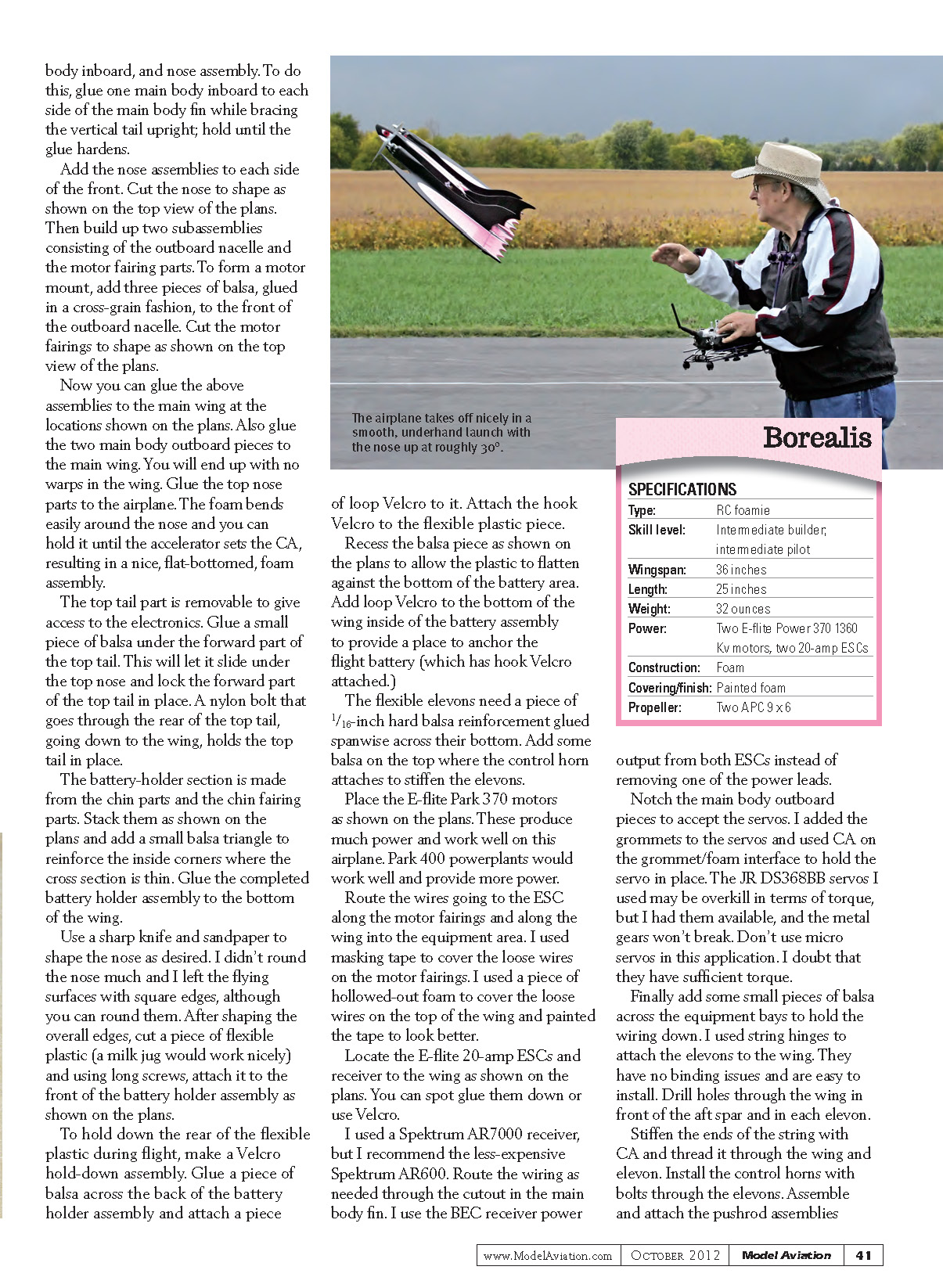
Trim the power to lift off on the first flights by reducing the throttle with the elevator slightly up. The airplane takes off nicely in a smooth, underhand launch with the nose up at roughly 30°. You may need to give a bit of additional up elevon during the initial part of the launch when the airspeed is low. I recommend that a friend provide the first launch for you, although I launched the airplane myself.
Start with a control surface position of approximately 1/8-inch up-elevon and adjust during flight to maintain level flight. The Borealis shown in the photos has a rudder, but I haven't convinced myself it is worth the effort because I rarely use it.
If you decide to add a rudder, be sure to brace the vertical tail on each side with a strong string that runs at roughly a 45° angle from the vertical tail down to the surface of the wing. Pull the string tight and CA it in place. If you don't, the bending moment from the deflected rudder may break the glue joint between the vertical tail and the wing.
With an E-flite 3s 2100 mAh LiPo battery positioned against the forward part of the battery area, the model should balance at the CG location shown on the plans. This is a conservative CG location and a good starting place. You may want to experiment with the CG position as you gain experience with the airplane's characteristics. Moving the CG aft will make the airplane more responsive to control inputs until an unstable point is reached.
Performance and handling
The finished airplane with a battery weighed exactly 2 pounds and the power level was measured at more than 250 watts. This gives a power loading of well beyond 100 watts per pound and promises good performance.
I fly the airplane with Landing Products electric propellers ranging from 8 x 6 to 9 x 6. I recommend starting with 9 x 6 counterrotating propellers, which will eliminate torque effects. This will give maximum thrust and speed. The motor temperatures at the end of a flight are cool, so the setup is fine.
I have flown the airplane with propellers rotating in the same direction—all that I had available at the time—and the Borealis flew fine. It only needed a bit of roll trim.
The airplane has no bad traits and looks great in the air. It is an unusual-looking planform and is a nice change from the usual airplanes seen at the flying field. Possessing a 36-inch wingspan, Borealis is a large flying wing and it grooves well. With the power available, the airplane will launch nicely with a smooth underhand launch; hold the nose up at roughly 30° and give it a toss.
The Borealis is a fast, maneuverable airplane that is easy to fly, and it looks delightful in the air. Before flying Borealis on your own, you should be able to fly a typical sport airplane without much effort.
The Borealis' low-speed handling is nice, possibly because of the spikes and the resulting vortex action. During landing the pilot can set up an approach angle of attack, or pitch angle, and control the exact touchdown spot with throttle control. Actual touchdown speed is slow.
The Borealis has an interesting look in the air and it is a nice-flying airplane with no bad habits.
—Ben Lanterman [email protected]
Sources
- Horizon Hobby
(800) 338-4639 www.horizonhobby.com
- Landing Products
(530) 661-0399 www.apcprop.com
Transcribed from original scans by AI. Minor OCR errors may remain.

