
Buhl Sport Airsedan
by Phillip S. Kent
I became aware of the Buhl Aircraft Company during the late 1950s; one of my American friends, Steve Ditta, sent me a Berkeley kit of the Buhl Pup.
This interesting little scale free-flight model was a fine flying machine. On one occasion it hooked a powerful thermal and flew out of sight.
My next contact with models of Buhl aircraft was through an article in our Aeromodeller magazine, which featured a Buhl Sport Airsedan designed by American modeler Hurst Bowers. From those plans—scaled up to a 72-inch wingspan—I built my first radio-control model years ago. The model flew well, but it was not very accurate. When some information about the full-scale aircraft came to light, I did a complete redesign of the model.
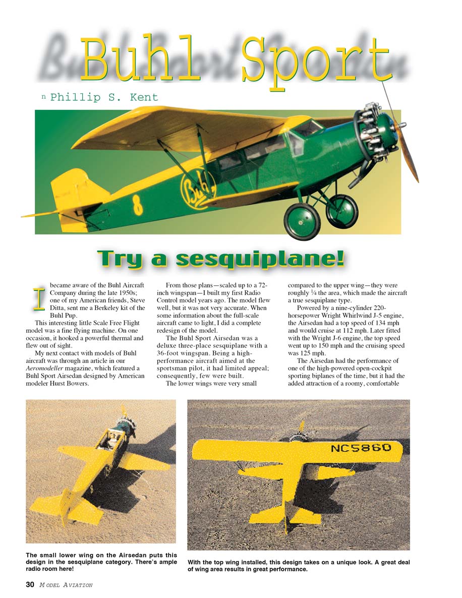
The Buhl Sport Airsedan was a deluxe three-place sesquiplane with a 36-foot wingspan. Being a high-performance aircraft aimed at the sportsman pilot, it had limited appeal; consequently, few were built. The lower wings were very small compared to the upper wing—they were roughly 1/4 the area, which made the aircraft a true sesquiplane.
Powered by a nine-cylinder 220-horsepower Wright Whirlwind J-5 engine, the Airsedan had a top speed of 134 mph and would cruise at 112 mph. Later fitted with the Wright J-6 engine, the top speed went up to 150 mph and the cruising speed was 125 mph.
The Airsedan had the performance of one of the high-powered open-cockpit sporting biplanes of the time, but it had the added attraction of a roomy, comfortable cabin for three and a payload big enough to allow the occupants to have ample baggage. The aircraft type took part in many of the competitive and record events of the time, with some success.
I got some useful information, including a drawing with color information about the full-scale aircraft from the June 1969 Sport Flying magazine and photographs from U.S. Civil Aircraft by Juptner.
The model is to 1/6 scale with a wingspan of 72 inches. The earlier model design was a similar scale and was flown using an O.S. 48 four-stroke engine. The later model—the subject of this article—is flying with an old open-rocker O.S. 60 four-stroke, but anything from a 52 to a 75 four-stroke should be fine.
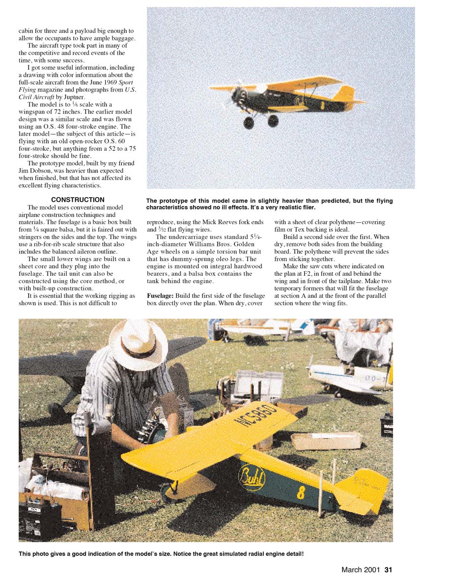
The prototype of this model came in slightly heavier than predicted, but the flying characteristics showed no ill effects. It’s a very realistic flier.
CONSTRUCTION
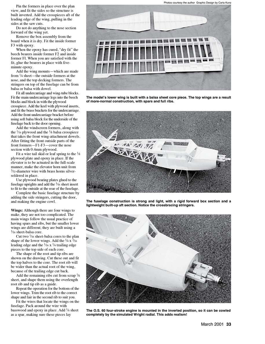
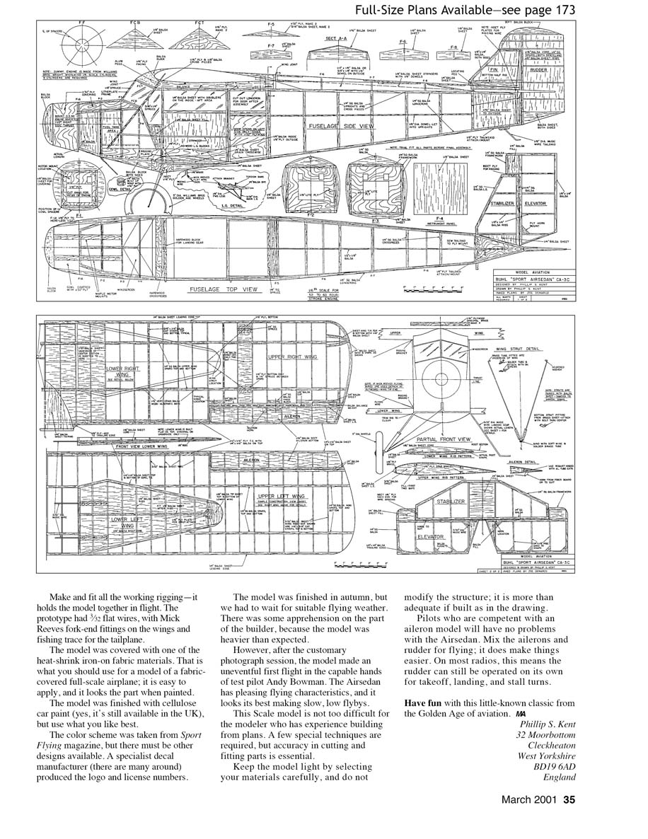
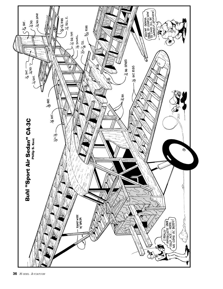
The model uses conventional model-airplane construction techniques and materials. The fuselage is a basic box built from 1/4 in sq balsa, but it is faired out with stringers on the sides and the top. The wings use a rib-for-rib scale structure that also includes the balanced aileron outline. The small lower wings are built on a sheet core and they plug into the fuselage. The tail unit can also be constructed using the core method, or with built-up construction.
It is essential that the working rigging as shown is used. This is not difficult to reproduce, using the Mick Reeves fork ends and 3/32 flat flying wires. The undercarriage uses standard 5 1/4-inch-diameter Williams Bros. Golden Age wheels on a simple torsion bar unit that has dummy-sprung oleo legs. The engine is mounted on integral hardwood bearers, and a balsa box contains the tank behind the engine.
Fuselage
- Build the first side of the fuselage box directly over the plan. When dry, cover with a sheet of clear polythene—covering film or Tex backing is ideal. Build a second side over the first. When dry, remove both sides from the building board. The polythene will prevent the sides from sticking together.
- Make the saw cuts where indicated on the plan at F2, in front of and behind the wing and in front of the tailplane. Make two temporary formers that will fit the fuselage at section A and at the front of the parallel section where the wing fits.
- With the sides over the formers, fit the 1/4 in sq top and bottom longerons and the 3/16 in sq cross-members on top and bottom. Join the nose pieces with the hardwood bearers for the engine. Add the 1/8 in sheet doublers each side in the nose area. Fit the 1/8 in sheet balsa on the bottom in the centre section under the wing.
- Build up the top and bottom of the rear fuselage with 1/8 in sq stringers, faired to the fuselage contours, then sheet the fuselage sides with 1/16 in sheet. When dry, sand the fuselage to shape and fit the 1/16 in ply firewall. Add the plywood tongue for the undercarriage.
- Rear fuselage top decking is built up from 1/16 in sheet with 1/8 in sq stringers forming the curved top. Fit the cowl assembly, mock up the engine and make the dummy motor rocker boxes from softwood. Cut the cockpit openings as indicated and fit the cockpits with the instrument panels and seats. The cabin top is built from sheet with the top longeron and stringers faired in. Fit the top decking and sand to shape. Finish the fuselage with 1/32 in sheet where necessary and sand smooth.
- Pin the formers in place over the plan view, and fit the sides so the structure is built inverted. Add the crosspieces aft of the leading edge of the wing, pulling in the sides at the saw cuts.
- Do not do anything to the nose section forward of the wing yet.
- Remove the box assembly from the board when it is dry. Fit the inside former F3 with epoxy. When the epoxy has cured, "dry fit" the beech bearers inside former F2 and inside former F1. When you are satisfied with the fit, glue the bearers in place with five-minute epoxy.
- Add the wing mounts — which are made from 1/4 in sheet — the outside formers at the nose, and the top decking formers. The stringers on top of the fuselage can be from balsa or balsa with dowel.
- Fit all undercarriage and wing-tube blocks. Fit the main undercarriage legs into the beech blocks and block in with the plywood crosspiece. Add the keel with plywood inserts, and fit the brass brackets for the undercarriage. Add the front undercarriage bracket before using soft balsa block for the underside of the fuselage back to the door opening.
- Add the windscreen formers, along with the 1/16 in plywood and the 1/8 in balsa crosspiece that takes the front wing-attachment dowels. After fitting the front outside parts of the front formers—F1–F3—cover the nose section with 0.4 mm plywood.
- Fit a wire tail skid or leaf spring to the 1/8 in plywood plate and epoxy in place. If the elevator is to be actuated in the full-scale manner, make the elevator horn unit from 3/32-diameter wire with brass horns silver-soldered in place.
- Use plywood bearing plates glued to the fuselage uprights and add the 1/16 in sheet insert to fit to the outside at the rear of the fuselage.
- Complete the basic fuselage structure by adding the side stringers, cutting the door, and making the engine cowl.
Wings
Although there are four wings to make, they are not too complicated. The main wings follow the usual practice of having spars and ribs, but the smaller lower wings are different; they are built using a 1/16 in sheet-balsa core.
- Cut two 1/16 in sheet-balsa cores to the plan shape of the lower wings. Add the 1/4 x 3/16 in leading edge and the 1/16 x 1/4 in trailing edge pieces to the top side of each core.
- The shape of the root and tip ribs are shown on the drawing. Cut these out and fit the top halves to the root. The root rib will be wider than the actual root of the wing, because of the trailing edge cut back.
- Add the remaining ribs cut from scrap 1/8 in sheet, and shape them using the overlength root rib and tip rib as a guide. Repeat the operation for the bottom of the lower wings. Trim the root rib to the correct shape and fair in the second rib to suit.
- Fit the wires that locate the wings on the fuselage. Pack around the wire with basswood and epoxy in place. Add 1/4 in sheet as a spar, making sure these pieces lay below the covering line. Add the balsa tips and plywood rigging inserts.
- Cut a plywood rib template; using it, produce 40 wing ribs from 3/32 in sheet balsa. Pin the front 1/4 in sq spar on the board. Place suitable packing pieces at the trailing edge and underneath the rear spar before fitting the ribs. Shorten the ribs where the ailerons are located before fitting.
- Glue the aileron spar and the leading and trailing edges in place. Fit the two 1/4 in sq top spars and then add the 1/16 in sheet webs where indicated.
- Build the ailerons on a 1/16 in sheet bottom, using the cutoff pieces of rib and a 1/4 in sheet spar. Fit the sheet balsa tips and build up with sheet or laminations at the outside.
- Both wings may be joined when they are at this stage. Block up the last full 3/4 in at the front spar and cut the spars at 90° to the building board. Fit the center ribs, then join the wings. Cut slots and fit the plywood dihedral braces at all spars and the leading edge.
- Fit the plywood wing-bolt retaining piece, then build up the rear fairing. The wing can be retained with one or two nylon bolts that fit into tapped holes in the plywood plate. Fit the plywood brace that carries the locating dowels for the wing into the central wing ribs.
- Return the wing to the blocking pieces and fit all the top capping strips, including the capping for the aileron spar. Note the direction of the grain. Fit the capping strips and sheeting to the underside of the wing. Cap the aileron ribs and add the balsa mass balances and hinge blocks.
- Make cutouts in the wings for the balances and the hinge setup. The drawing shows details of the wing section with Robart hinges in position.
- Fix the wing to the fuselage for final fitting of the block-balsa front fairing and the built-up rear fairing.
Tail Assembly
- The fin and rudder use a 1/16 in sheet-balsa core. Cut out and mark the positions of the ribs on both items. Fit the 1/4 in sq spar and the 1/4 x 1/8 in leading edge on the fin, then fit the 1/8 in sheet ribs.
- The rudder has a 1/4 in sq spar, which should be fitted first. Add the ribs and the soft-balsa block capping. Repeat these operations on each side.
- You can use the core method of construction on the tailplane, but the prototype model had a built-up structure. Build the parts directly over the plan, using the wood sizes indicated.
- Pack up the trailing edge of the elevator. When complete, sand to the section shown on the drawing.
Gathering the Loose Ends
The dummy engine is one of the main features of the model. The prototype had 1/6-scale Williams Bros. Wright Whirlwind cylinders fitted to the removable cowl. It is easy to hide the model power unit in the cowl if the engine is mounted inverted. The prototype model originally had an old O.S. 60 open-rocker four-stroke engine, but it has been replaced with an up-to-date version.
The model should weigh approximately 6 1/2 pounds if built per the plan. The prototype was heavier, at more than eight pounds, but it did not affect the performance.
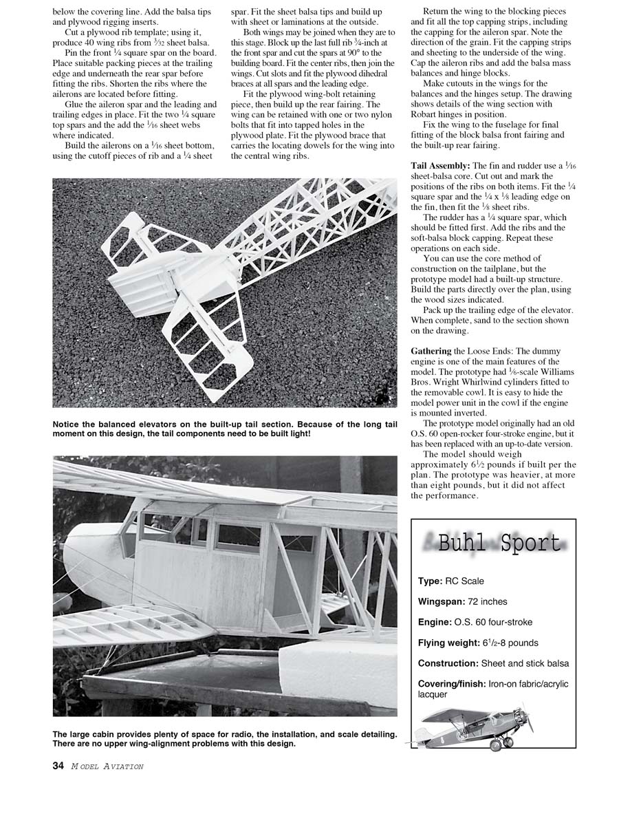
Buhl Sport — Specifications
- Type: RC scale
- Wingspan: 72 inches
- Engine: O.S. 60 four-stroke (typical; 52–75 four-strokes acceptable)
- Flying weight: 6 1/2–8 pounds
- Construction: Sheet-and-stick balsa
- Covering/finish: Iron-on fabric / acrylic lacquer
Make and fit all the working rigging — it holds the model together in flight. The prototype had 3/32 in flat wires, with Mick Reeves fork-end fittings on the wings and fishing trace for the tailplane.
The model was covered with one of the heat-shrink iron-on fabric materials. That is what you should use for a model of a fabric-covered full-scale airplane; it is easy to apply, and it looks the part when painted. The model was finished with cellulose car paint (yes, it's still available in the UK), but use what you like best.
The colour scheme was taken from Sport Flying magazine, but there must be other designs available. A specialist decal manufacturer produced the logo and license numbers.
The model was finished in autumn, but we had to wait for suitable flying weather. There was some apprehension on the part of the builder, because the model was heavier than expected. However, after the customary photograph session, the model made an uneventful first flight in the capable hands of test pilot Andy Bowman. The Airsedan has pleasing flying characteristics, and it looks its best making slow, low flybys.
This scale model is not too difficult for the modeler who has experience building from plans. A few special techniques are required, but accuracy in cutting and fitting parts is essential. Keep the model light by selecting your materials carefully, and do not modify the structure; it is more than adequate if built as in the drawing.
Pilots who are competent with an aileron model will have no problems with the Airsedan. Mix the ailerons and rudder for flying; it does make things easier. On most radios, this means the rudder can still be operated on its own for takeoff, landing, and stall turns.
Have fun with this little-known classic from the Golden Age of aviation.
Phillip S. Kent 32 Moorbottom Cleckheaton West Yorkshire BD19 6AD England
Buhl "Sport Air Sedan" CA-3C
Phillip S. Kent
Transcribed from original scans by AI. Minor OCR errors may remain.

