
Build a Centigram Balance Scale
by Roger Carignan
At one time or another, most aircraft modelers have the need to weigh various parts of their models as they are being built, to help determine the final "all-up" weight of the completed project.
With the widespread interest in smaller Radio Control (RC) indoor and park flyers, weighing components gets into the domain of the Free Flight rubber-powered models.
Throughout the years, my 30-pound-capacity baby scale and 500-gram dieter's scale served me well for the types of models I built. The dieter's scale had divisions every two grams; with some care, weights to the nearest half gram could be resolved with this device.
Looking for sensitive scales on the retail market, I would have to spend $100 or more for digital scales that only had 0.1-gram increments.
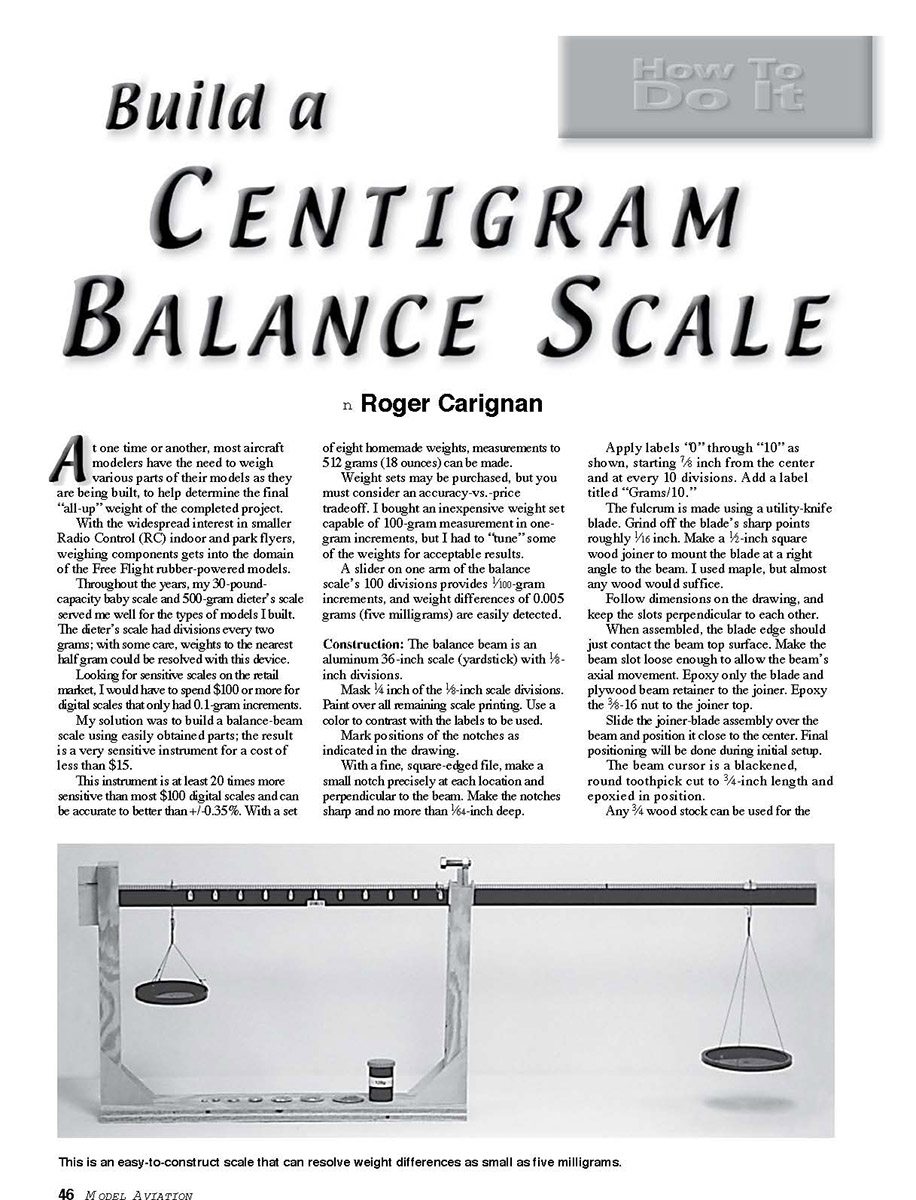
My solution was to build a balance-beam scale using easily obtained parts; the result is a very sensitive instrument for a cost of less than $15.
This instrument is at least 20 times more sensitive than most $100 digital scales and can be accurate to better than +/-0.35%. With a set of eight homemade weights, measurements to 512 grams (18 ounces) can be made.
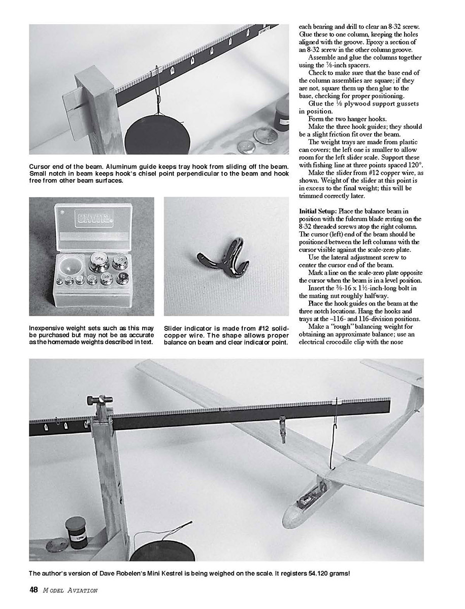
Weight sets may be purchased, but you must consider an accuracy-vs.-price tradeoff. I bought an inexpensive weight set capable of 100-gram measurement in one-gram increments, but I had to "tune" some of the weights for acceptable results.
A slider on one arm of the balance scale's 100 divisions provides 1/100-gram increments, and weight differences of 0.005 grams (five milligrams) are easily detected.
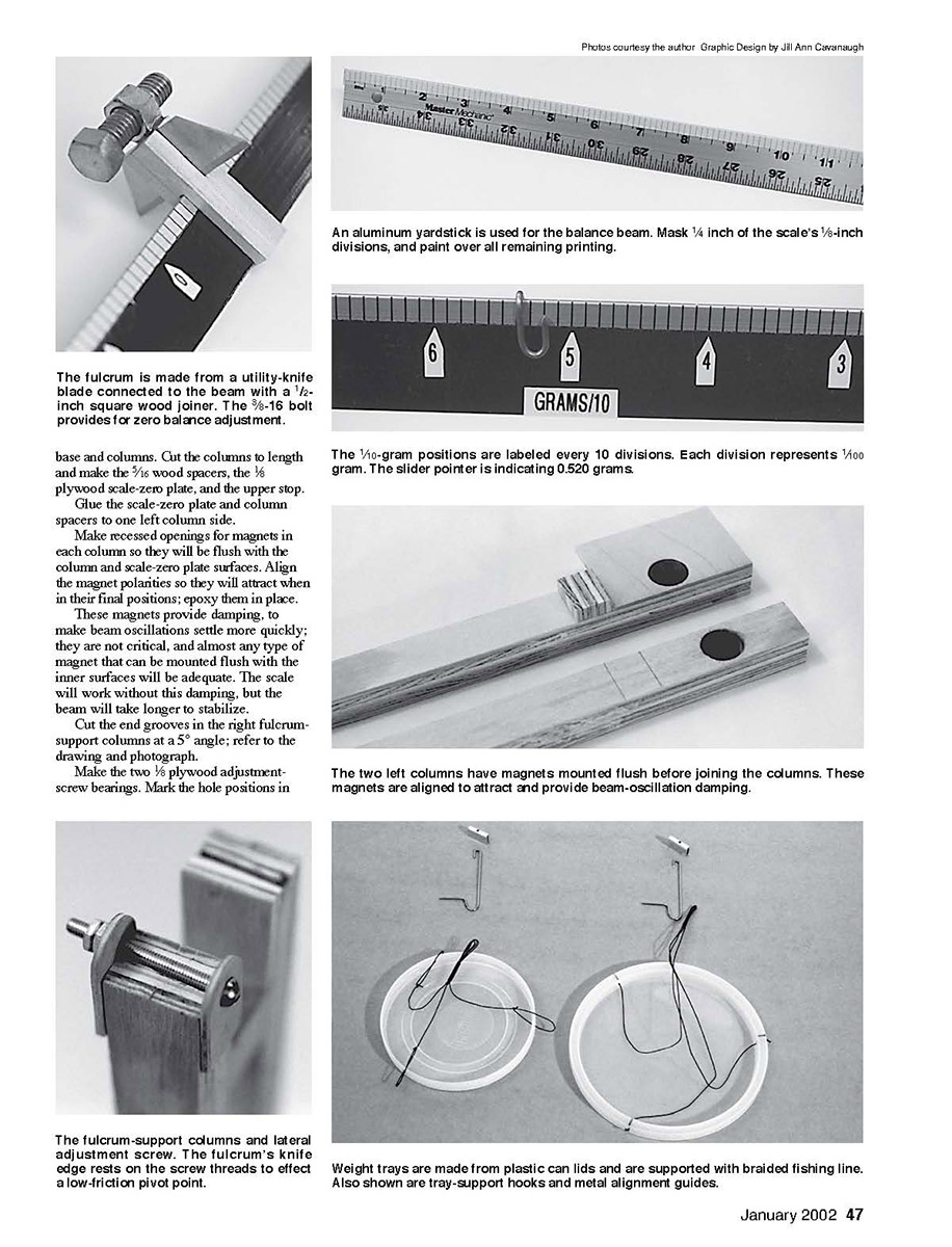
Construction: The balance beam is an aluminum 36-inch scale (yardstick) with 1/8-inch divisions.
Mask 1/4 inch of the 1/8-inch scale divisions. Paint over all remaining scale printing. Use a color to contrast with the labels to be used.
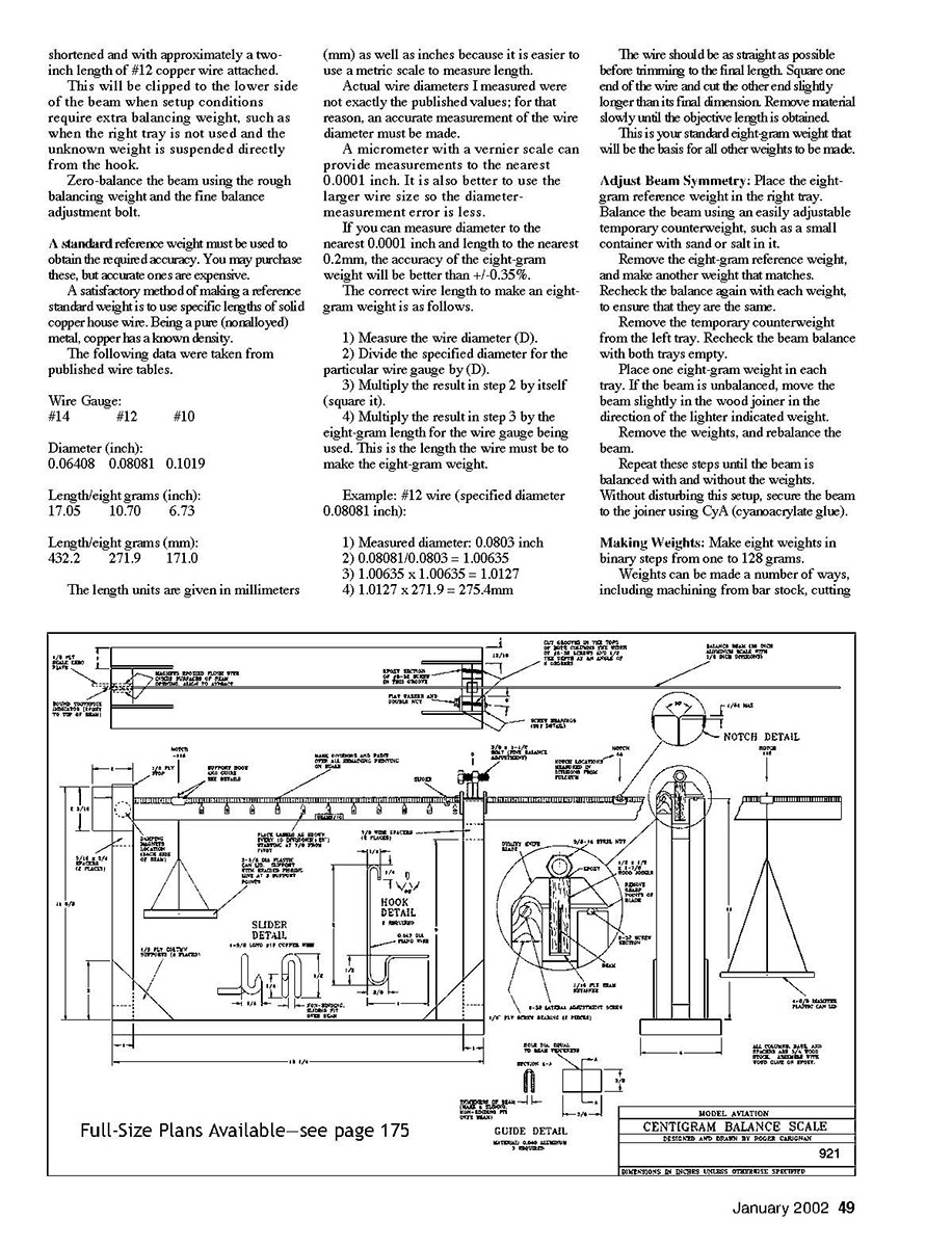
Mark positions of the notches as indicated in the drawing.
With a fine, square-edged file, make a small notch precisely at each location and perpendicular to the beam. Make the notches sharp and no more than 1/64-inch deep.
Apply labels "0" through "10" as shown, starting 7/8 inch from the center and at every 10 divisions. Add a label titled "Grams/10".
The fulcrum is made using a utility-knife blade. Grind off the blade's sharp points roughly 1/16 inch. Make a 1/2-inch square wood joiner to mount the blade at a right angle to the beam. I used maple, but almost any wood will suffice.
Follow dimensions on the drawing, and keep the slots perpendicular to each other. When assembled, the blade edge should just contact the beam top surface. Make the beam slot loose enough to allow the beam's axial movement. Epoxy only the blade and plywood beam retainer to the joiner. Epoxy the 3/8-inch nut to the joiner top.
Slide the joiner-blade assembly over the beam and position it close to the center. Final positioning will be done during initial setup.
The beam cursor is a blackened, round toothpick cut to 3/4-inch length and epoxied in position.
Any 3/4-inch wood stock can be used for the base and columns. Cut the columns to length and make the 5/16 wood spacers, the 1/8 plywood scale-zero plate, and the upper stop.
Glue the scale-zero plate and column spacers to one left column side.
Make recessed openings for magnets in each column so they will be flush with the column and scale-zero plate surfaces. Align the magnet polarities so they will attract when in their final positions; epoxy them in place.
These magnets provide damping, to make beam oscillations settle more quickly; they are not critical, and almost any type of magnet that can be mounted flush with the inner surfaces will be adequate. The scale will work without this damping, but the beam will take longer to stabilize.
Cut the end grooves in the right fulcrum-support columns at a 5° angle; refer to the drawing and photograph.
Make the two 1/8 plywood adjustment-screw bearings. Mark the hole positions in each bearing and drill to clear an 8-32 screw. Glue these to one column, keeping the holes aligned with the groove. Epoxy a section of an 8-32 screw in the other column groove.
Assemble and glue the columns together using the 7/8-inch spacers.
Check to make sure that the base end of the column assemblies are square; if they are not, square them up then glue to the base, checking for proper positioning.
Glue the 1/8 plywood support gussets in position.
Form the two hanger hooks.
Make the three hook guides; they should be a slight friction fit over the beam.
The weight trays are made from plastic can covers; the left one is smaller to allow room for the left slider scale. Support these with fishing line at three points spaced 120°.
Make the slider from #12 copper wire, as shown. Weight of the slider at this point is in excess to the final weight; this will be trimmed correctly later.
Initial Setup: Place the balance beam in position with the fulcrum blade resting on the 8-32 threaded screws atop the right column. The cursor (left) end of the beam should be positioned between the left columns with the cursor visible against the scale-zero plate.
Use the lateral adjustment screw to center the cursor end of the beam.
Mark a line on the scale-zero plate opposite the cursor when the beam is in a level position.
Insert the 3/16 x 1-1/4-inch-long bolt in the mating nut roughly halfway.
Place the hook guides on the beam at the three notch locations. Hang the hooks and trays at the -116- and 116-division positions.
Make a "rough" balancing weight for obtaining an approximate balance; use an electrical crocodile clip with the nose over the hook to give more leverage than the plain hook.
With the beam roughly balanced, tighten the three 8-32 screws holding the fulcrum blade assembly in place. Remove the rough weight and slide the slider to zero. Clamp the left end of the beam to the base. Place the weight set on the right tray. Add or remove small pieces trimmed from the slider until the beam returns to the level position at zero. Adjust the hanger position for best balance, and make sure the friction guides allow smooth movement. Shorten the slider and trim it to approximately a two-inch length of #12 copper wire attached. This will be clipped to the lower side of the beam when setup conditions require extra balancing weight, such as when the right tray is not used and the unknown weight is suspended directly from the hook.
Zero-balance the beam using the rough balancing weight and the fine balance adjustment bolt.
A standard reference weight must be used to obtain the required accuracy. You may purchase these, but accurate ones are expensive.
A satisfactory method of making a reference standard weight is to use specific lengths of solid copper house wire. Being a pure (nonalloyed) metal, copper has a known density.
The following data were taken from published wire tables.
Wire Gauge: #14 #12 #10
Diameter (inch): 0.06408 0.08081 0.1019
Length/eight grams (inch): 17.05 10.70 6.73
Length/eight grams (mm): 432.2 271.9 171.0
The length units are given in millimeters (mm) as well as inches because it is easier to use a metric scale to measure length.
Actual wire diameters I measured were not exactly the published values; for that reason, an accurate measurement of the wire diameter must be made.
A micrometer with a vernier scale can provide measurements to the nearest 0.0001 inch. It is also better to use the larger wire size so the diameter measurement error is less.
If you can measure diameter to the nearest 0.0001 inch and length to the nearest 0.2 mm, the accuracy of the eight-gram weight will be better than +/-0.35%.
The correct wire length to make an eight-gram weight is as follows.
- Measure the wire diameter (D).
- Divide the specified diameter for the particular wire gauge by (D).
- Multiply the result in step 2 by itself (square it).
- Multiply the result in step 3 by the eight-gram length for the wire gauge being used. This is the length the wire must be to make the eight-gram weight.
Example: #12 wire (specified diameter 0.08081 inch):
1) Measured diameter: 0.0803 inch 2) 0.08081/0.0803 = 1.00635 3) 1.00635 x 1.00635 = 1.0127 4) 1.0127 x 271.9 = 275.4 mm
The wire should be as straight as possible before trimming to the final length. Square one end of the wire and cut the other end slightly longer than its final dimension. Remove material slowly until the objective length is obtained. This is your standard eight-gram weight that will be the basis for all other weights to be made.
Adjust Beam Symmetry: Place the eight-gram reference weight in the right tray. Balance the beam using an easily adjustable temporary counterweight, such as a small container with sand or salt in it.
Remove the eight-gram reference weight, and make another weight that matches. Recheck the balance again with each weight, to ensure that they are the same.
Remove the temporary counterweight from the left tray. Recheck the beam balance with both trays empty.
Place one eight-gram weight in each tray. If the beam is unbalanced, move the beam slightly in the wood joiner in the direction of the lighter indicated weight.
Remove the weights, and rebalance the beam.
Repeat these steps until the beam is balanced with and without the weights. Without disturbing this setup, secure the beam to the joiner using CyA (cyanoacrylate glue).
Making Weights: Make eight weights in binary steps from one to 128 grams.
Weights can be made a number of ways, including machining from bar stock, cutting lengths of wire, using sand or any granular material of sufficient density in small containers, using coin stacks, and casting low-melting-temperature metal.
I made my weights using a half-pound roll of lead-free plumber’s solder for the seven weights ranging from one to 64 grams. The solder weight is roughly 1.3 grams per inch.
For each weight, cut the solder so its weight is slightly higher than the reference being used.
Melt the solder into a globular shape using the bottom of an empty aluminum beverage can. I squashed the can’s top end in a vise that also supported the can during the operation.
Melt the solder using a propane torch. When cool, mark the weight with its value in grams. Trim this weight using sandpaper or a file. Remove material more slowly when nearing its final weight.
Whatever the weight-making method, use the following procedure.
- The eight-gram weight is made by placing the eight-gram reference weight in the right tray and making a matching weight.
- The 16- through 128-gram weights: After each new weight is made, add this to the right tray with the other weights to make the next (two times) higher weight.
- The 128-gram weight: If using the solder method, there will be insufficient solder remaining from the half-pound roll to make the 128-gram weight. I used pennies in a plastic 35mm film container. This was also a lower-cost solution; approximately 45 coins were used.
- The four- through one-gram weights: Change the right tray hook position to the 58-division position. With no weights in the trays, rebalance the beam using the rough balance weight and fine-adjustment bolt.
Place the eight-gram reference in the right tray, and make a new (four-gram) weight for the left tray that will balance the beam.
Repeat this step for each half lower weight using each new weight in the right tray until the one-gram weight is made.
The “One-Gram” Slider: Reposition the right tray back to the 116-division position and rezero the beam.
Place the one-gram weight in the right tray and the slider with the pointer at the 9.3 position (100 divisions from the fulcrum) on the left scale.
Adjust the slider weight to balance the beam.
Remove the one-gram right tray weight and move the slider pointer to the “0” position and rezero the beam balance.
Place the one-gram weight in the right tray and move the slider pointer to “10” on the left scale.
The beam should be balanced in this condition; if it’s not, make fine adjustments to the slider weight and beam zero balance until the “0” and “10” positions of the slider coincide with the zero and one-gram right-tray weight conditions.
Using the Scale: With the balance scale and its set of weights completed, you will be able to detect weight changes as small as five milligrams (half division on the slider).
With the right-tray position at 116 divisions, weights to 256 grams (nine ounces) can be measured. With the right-tray position at 58 divisions, the range can be doubled to 18 ounces.
Remember to rebalance the beam with no weights before making a measurement.
Small air currents will cause beam movement. Use the scale in an area free from moving air. Making fine measurements may require you to hold your breath or shield the trays to keep them free from airflow. MA
Roger Carignan 39 Glen Rd. Wilmington MA 01887 [email protected]
Sources of weight sets:
Transcribed from original scans by AI. Minor OCR errors may remain.

