
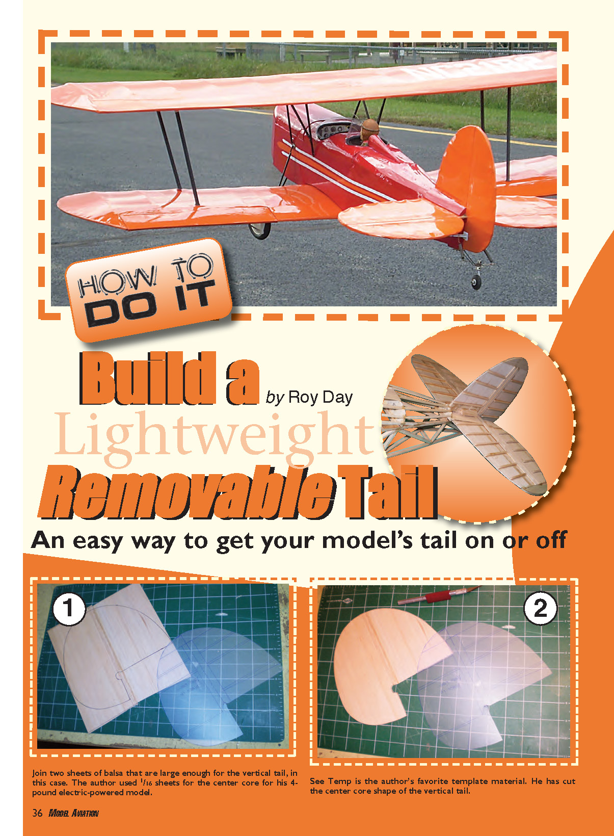
Build a Lightweight Removable Tail - 2010/06
By Roy Day
An easy way to get your model’s tail on or off
There are many techniques to use to build the tail section of a model aircraft. In every case, emphasis must be on keeping it light in weight. One method I have used through the years for a range of airplane sizes uses a center core of sheet stock, false ribs, and doublers. This system is easy to apply to any shape of tail, whether your subject is scale or not.
Following the steps outlined below, you can make the tail removable with a single nylon bolt for ease of transportation or to allow adjustments such as changing stabilizer incidence.
Materials and basic components
- Center core of sheet stock
- 1/8-inch buildup material (sheet)
- 1/8-inch square false ribs
- 1/8-inch doublers (strips)
- 1/8-inch plywood section, braced by diagonal stock (for bolt block)
- 1/8-inch alignment dowel pegs (LE peg for fin, bottom peg for stabilizer)
- Nylon attachment bolt (size may vary; #8 used as example)
- Elevator connector wire or dowel
- 2-ounce fiberglass cloth (for reinforcing elevator dowel)
- Medium-grit sanding block
- Clamps, drill, tap, saw
Construction and assembly steps
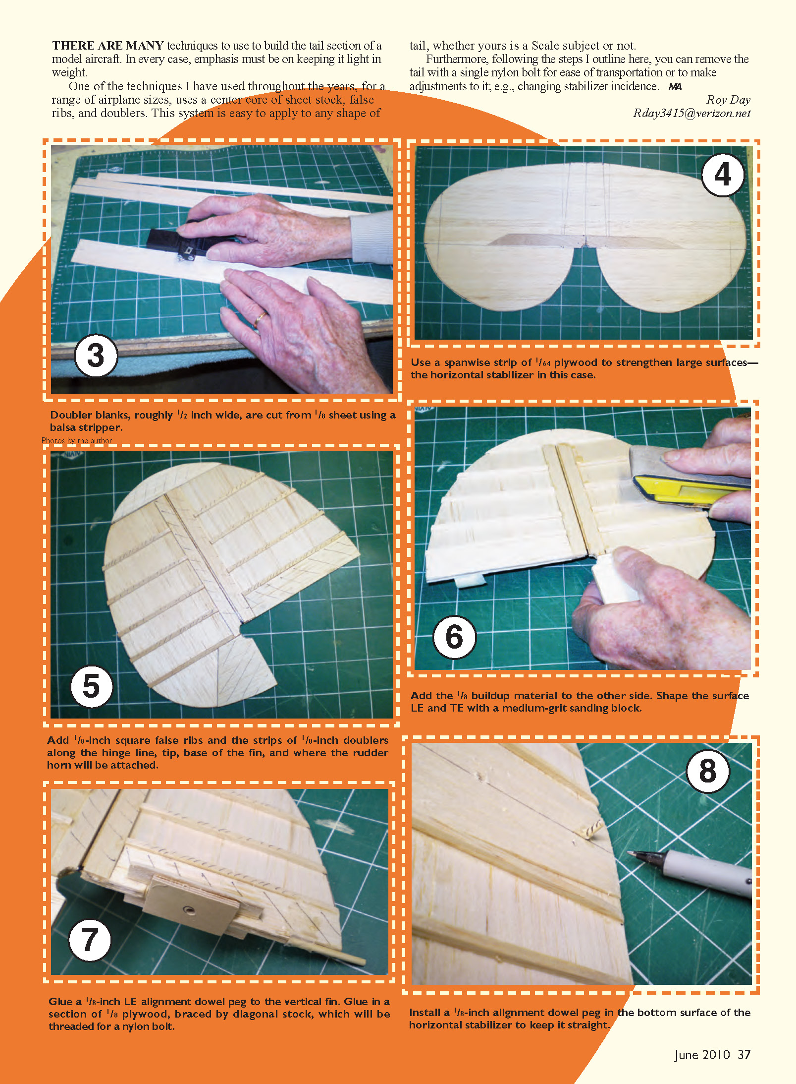
- Build the center core from sheet stock and add false ribs and doublers as required to achieve the tail shape. Keep all structure as light as possible.
- Glue the 1/8-inch buildup material to one side, then add the 1/8-inch buildup material to the other side. Shape the leading edge (LE) and trailing edge (TE) with a medium-grit sanding block.
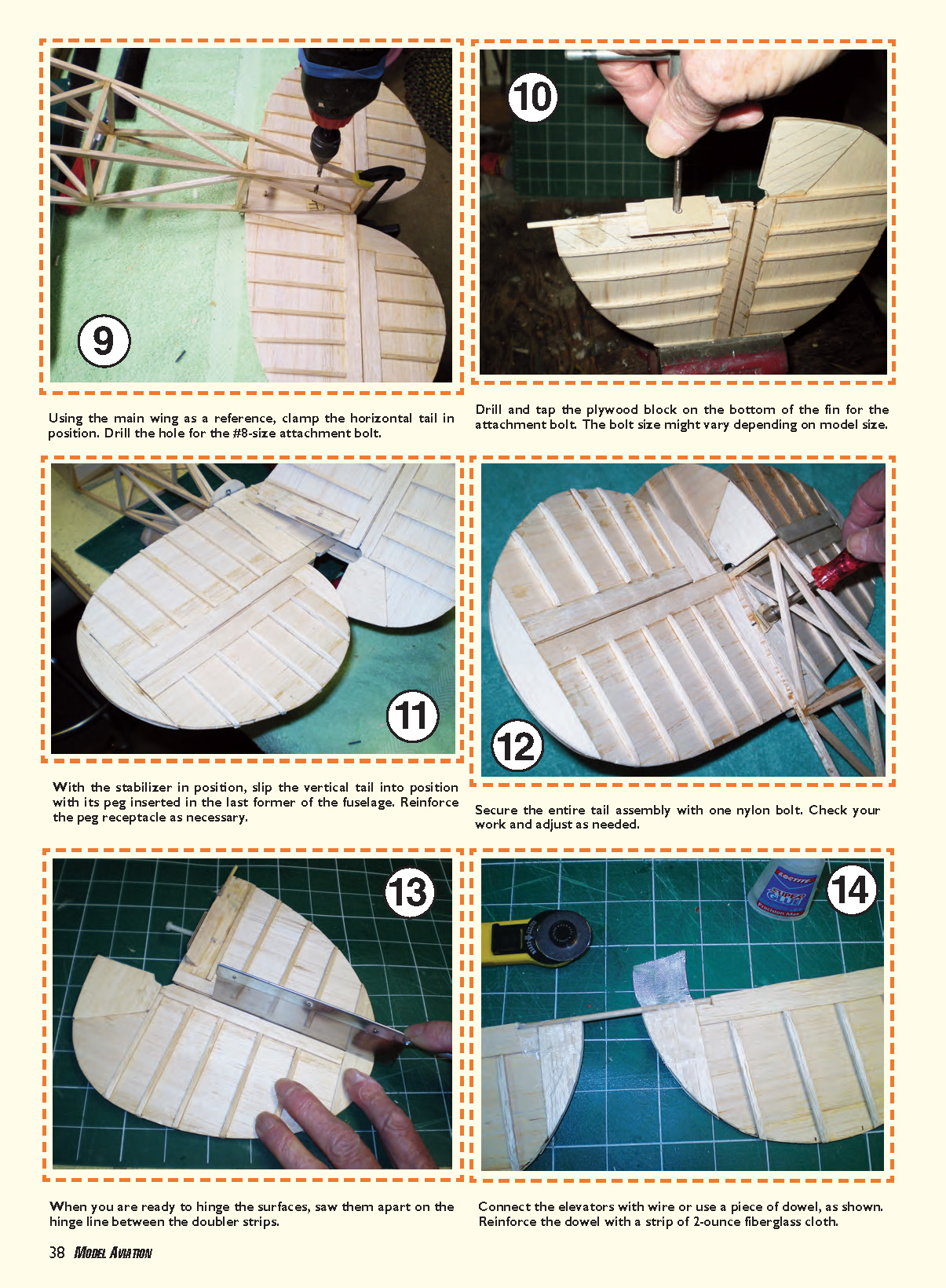
- Glue a 1/8-inch LE alignment dowel peg to the vertical fin.
- Glue in a section of 1/8-inch plywood, braced by diagonal stock, which will be threaded for a nylon bolt. Drill and tap this plywood block for the attachment bolt; the bolt size might vary depending on model size (a #8-size attachment bolt is a common example).
- Add 1/8-inch square false ribs and strips of 1/8-inch doublers along the hinge line, tip, base of the fin, and where the rudder horn will be attached.
- Install a 1/8-inch alignment dowel peg in the bottom surface of the horizontal stabilizer to keep it straight.
- Using the main wing as a reference, clamp the horizontal tail in position. Drill the hole for the attachment bolt through the stabilizer and into the plywood block you prepared.
- With the stabilizer in position, slip the vertical tail into position with its LE peg inserted in the last former of the fuselage. Reinforce the peg receptacle as necessary.
- Secure the entire tail assembly with one nylon bolt. Check alignment and adjust as needed.
Final steps: hinging and controls
- When you are ready to hinge the surfaces, saw them apart on the hinge line between the doubler strips.
- Connect the elevators with wire or use a piece of dowel, as shown in the reference. Reinforce the dowel with a strip of 2-ounce fiberglass cloth to strengthen the joint.
Notes
- Keep all components as light as practical while maintaining necessary strength.
- Bolt size and exact construction details may be adjusted for model scale and expected loads.
Transcribed from original scans by AI. Minor OCR errors may remain.

