
Build a Propeller Pitch Gauge
by Don Ogren
HAVE YOU EVER noticed that after you break a propeller and replace it with another propeller that is the same brand, size, and pitch, the model sometimes flies differently? The reason is simple: the propellers are different. It's easy to verify the same diameter when replacing a propeller, but confirming the pitch is more difficult.
Different propellers make a difference in the way airplanes fly. In RC sport flying we could seldom care less. After a bad landing we stick on a similar propeller and have our model back in the air as soon as we straighten the landing gear.
In a speed event such as Pylon Racing or in competitive CL or RC Aerobatics, the need for consistent and optimum performance requires that the propellers be consistently optimal. If we can't detect the differences in propellers and select the best, we won't be able to predict the outcome of our pending flights.
At the 2002 Brodak Fly-In I bought a few wood 10 x 6 propellers and found them (measuring on a crudely made pitch gauge) to have pitches of roughly 5.5 inches (at midblade). Several of the propellers were marked as having 6-inch pitches, but none did.
So the question arises: Where does a manufacturer measure the pitch for determining what numbers go on the propeller?
When you measure the pitch of propellers, you may come to the same conclusion I have: Who really cares? As long as one has the same pitch as another at the same blade station, we should expect consistent results in the air, in CL lap times, and in performance in all our models (while other variables remain constant).
Pitch-gauge sources are few. Then when we research the neat features and prices, we might reason that we've gotten along without one for umpteen years, so why lay out big bucks for such a device now? Aren't there any good, inexpensive pitch gauges?
I started to think about this, and being a mechanical engineer who still enjoys a design challenge, it didn't take too long for me to come up with an idea or two. The objective was to design a pitch gauge that would be simple to use, give accurate results, and cost less than those available.
The usual expectation is that something that is simple and less expensive won't do the job of the expensive gadgets. I would have to be careful to try to design this concept away.
Pitch gauges I had seen on the market did a great job. They indicated the pitch angle at a radius/position on the blade, which I'll refer to as a "station," and the pitch for any given blade station.
However, I didn't like the common feature of most gauges that required the propeller to be mounted front-side up. That meant the blade angle had to be read from the bottom side of the propeller, which was hard to see.
My approach to a design was to look at the flat portion of the blade (the back side of the propeller would face up). The angle indicator would rest on the blade and be easy to see.
What could be simpler than that? And why should something cost more than a few hours of shop time and a few bucks to make, with most parts fashioned from materials that could be found in most modelers' scrap boxes?
Design criteria
- Make it small enough to store easily.
- Make it cover the most often used propeller-diameter range for a variety of sport fliers: 6–20 inches.
- Make it so it could be constructed in a modeler's workshop.
- Make it without bells and whistles. Use a "pitch chart" plotted in blade angle vs. pitch instead of reading it directly on the pitch gauge (a compromise)—a feature that could be added later.
- Make it easy to use.
Without describing what the prototype gauge looked like, I'll just tell you that it worked and proved many points. My objective of simplicity was achieved in the final design, which is presented here.
Materials and Construction
The base is nominal 1 x 3-inch select pine—actually 3/4 x 2-1/2 inches—cut to a length of 8 inches. The slots for the angle indicator are cut 3/16 inch deep at locations of 2.0, 2.5, 3.0, 3.5, 4.0, 4.5, 5.0, and 5.5 inches, measured from the hub center (the center of the 1/4-inch-diameter hole for the propeller mounting screw).
I used a Dremel table saw to cut the 1/16-inch slots perpendicular to the propeller centerline at a constant depth. Careful measurement and setup while sawing resulted in accurately spaced blade stations.
A Dremel saw blade cuts slightly less than 1/16 inch, so I used tape on the saw blade to make it wobble enough to allow the 1/16-inch plywood indicator to slide in the slots. This range of stations will accommodate 8- to 20-inch-diameter propellers.
The propeller mounting screw is a 1/4 x 2-1/2-inch-long carriage bolt, pressed into a counterbored hole in the base. A washer and a wing nut hold the propeller in place.
Propeller spacers, 3/16-inch and 1/4-inch thick and 1 inch in diameter, are cut from plywood to raise the propeller off the base. In most cases this allows the angle indicator to be moved from station to station without having to loosen the wing nut. The thinner spacer can be used with lower-pitched propellers.
The angle indicator is cut from 1/16-inch plywood, which fits the base slots. I selected 0.047-inch-diameter wire simply because it fit the E-Z adjust connector I found in my collection of parts. Probably the most common size of connector will have larger holes for pushrod-size wire; that size connector would be okay to use, but I recommend using wire that is smaller than 1/16 inch in diameter for ease of bending. I filed a point on the end of the wire for a more precise reading.
Also, the pivot point of the connector, the wire, and the protractor's "0" need to be in horizontal alignment with the reference slots on the base.
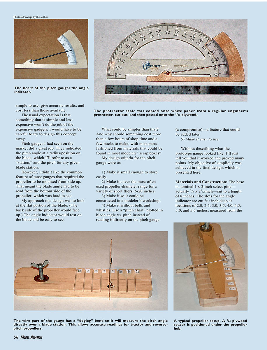
The protractor scale was copied onto white paper from a regular engineer's protractor, cut out, and then pasted onto the 1/16-inch plywood angle indicator. Attach the angle scale with a glue stick and cover with clear tape for protection.
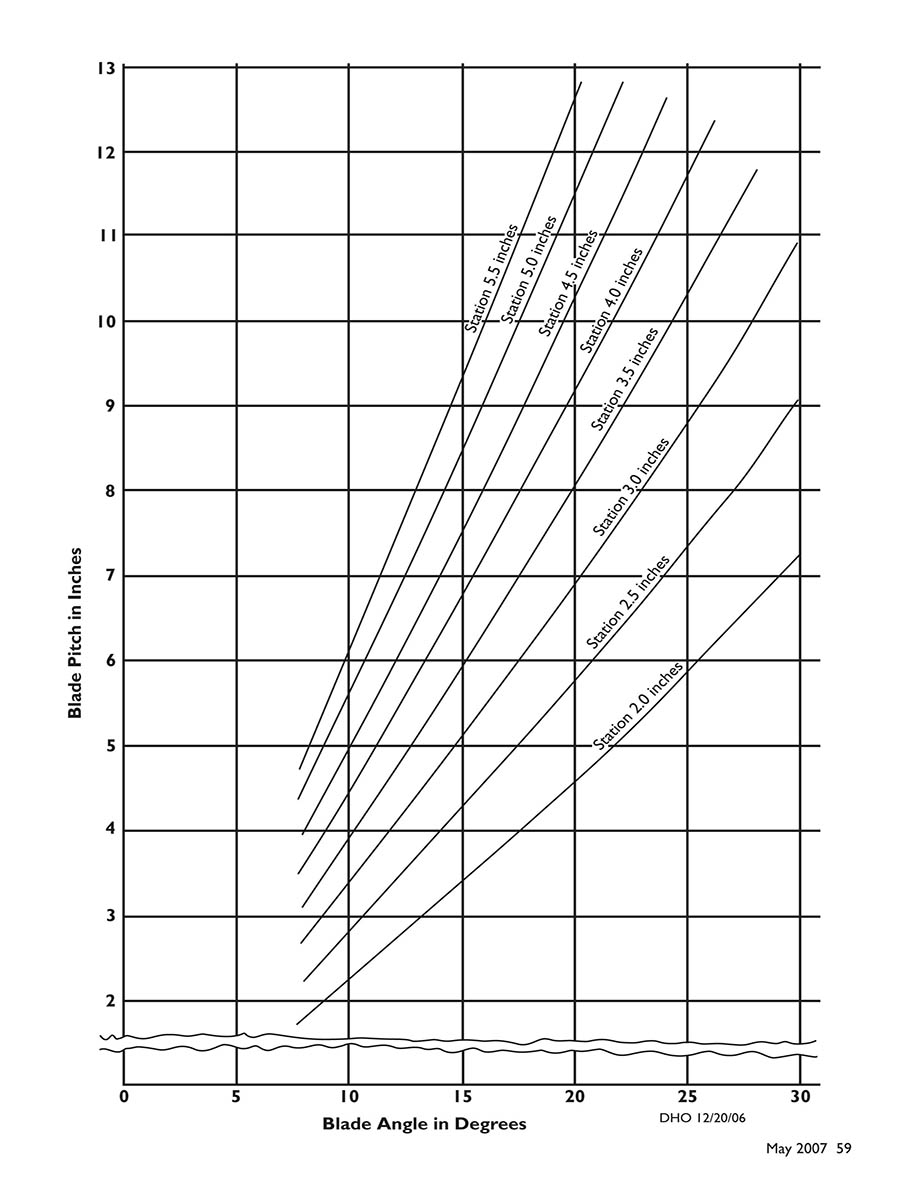
The pitch chart has a graphed line for each blade station. I made calculations and then plotted the "y" coordinates for every 2° of pitch for each station. This isn't as much work as it looks because the circular (one revolution) distance of each station is a constant and is simply multiplied by the tangent of the angles.
Construction summary (parts)
- Base: 3/4 x 2-1/2 x 8 inches, select pine.
- Slots: 1/16-inch wide, 3/16-inch deep at stations 2.0, 2.5, 3.0, 3.5, 4.0, 4.5, 5.0, 5.5 inches from hub center.
- Mounting screw: 1/4 x 2-1/2-inch carriage bolt (countersunk on bottom).
- Spacers: plywood, 3/16-inch and 1/4-inch thick x 1-inch diameter.
- Angle indicator: 1/16-inch aircraft plywood.
- Indicating wire: 0.047-inch diameter, filed to a point; fits E-Z adjust connector.
- Protractor scale: paper copy of an engineer's protractor, glued and taped to the angle indicator.
Using the Pitch Gauge
- Center the propeller on the base over the 1/4-inch mounting bolt and secure it with the washer and wing nut. Use a plywood spacer as needed to raise the hub.
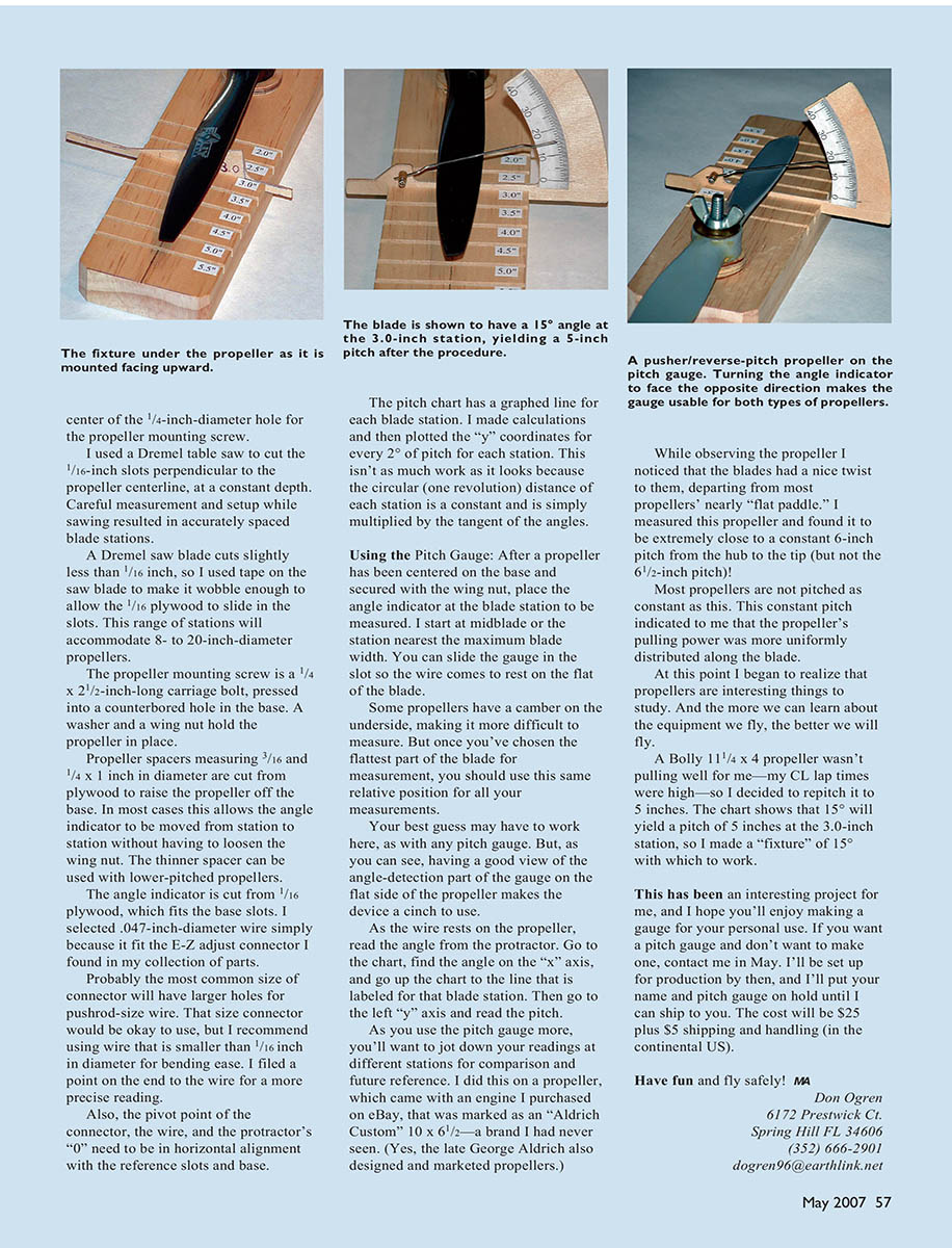
- Place the angle indicator in the slot corresponding to the blade station you wish to measure. I start at midblade or the station nearest the maximum blade width.
- Slide the gauge in the slot so the wire comes to rest on the flat of the blade. Choose the flattest part of the blade for consistency—some propellers have camber on the underside, so use the same relative position for all measurements.
- As the wire rests on the propeller, read the blade angle from the protractor (degrees).
- Go to the pitch chart, find the angle on the x-axis, move up to the line labeled for that blade station, then read the pitch from the y-axis (inches).
- Record readings for different stations for comparison and future reference.
Having a good view of the angle-detection part of the gauge on the flat side of the propeller makes the device a cinch to use. The wire can be bent with a "dogleg" so it measures the pitch angle directly over a blade station; this allows accurate readings for tractor and reverse-pitch propellers.
Example measurements and observations
- I measured an "Aldrich Custom" 10 x 6-1/2 propeller (a brand I had not seen before) and found it to be extremely close to a constant 6-inch pitch from hub to tip (but not the 6-1/2-inch pitch marked on it). This constant pitch suggested the pulling power was more uniformly distributed along the blade.
- I had a Bolly 11-1/4 x 4 propeller that wasn't pulling well (my CL lap times were high), so I decided to repitch it to 5 inches. The chart shows that 15° yields a pitch of 5 inches at the 3.0-inch station, so I made a 15° fixture to work from.
Propellers are interesting to study. The more we learn about the equipment we fly, the better we will fly.
Have fun and fly safely! MA
Don Ogren 6172 Prestwick Ct. Spring Hill, FL 34606 (352) 666-2901 [email protected]
If you want a pitch gauge and don't want to make one, contact me in May. I'll be set up for production by then, and I'll put your name and pitch gauge on hold until I can ship to you. The cost will be $25 plus $5 shipping and handling (continental US).
Diagrams, parts and captions
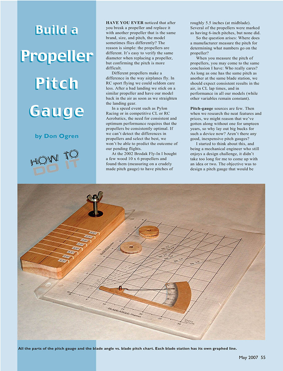
- All the parts of the pitch gauge and the blade angle vs. blade pitch chart. Each blade station has its own graphed line.
- A typical propeller setup: a 1/4-inch plywood spacer is positioned under the propeller hub. The wire part of the gauge has a "dogleg" bend so it will measure the pitch angle directly over a blade station. This allows accurate readings for tractor and reverse-pitch propellers.
- The heart of the pitch gauge: the angle indicator. The protractor scale was copied onto white paper from a regular engineer's protractor, cut out, and then pasted onto the 1/16-inch plywood.
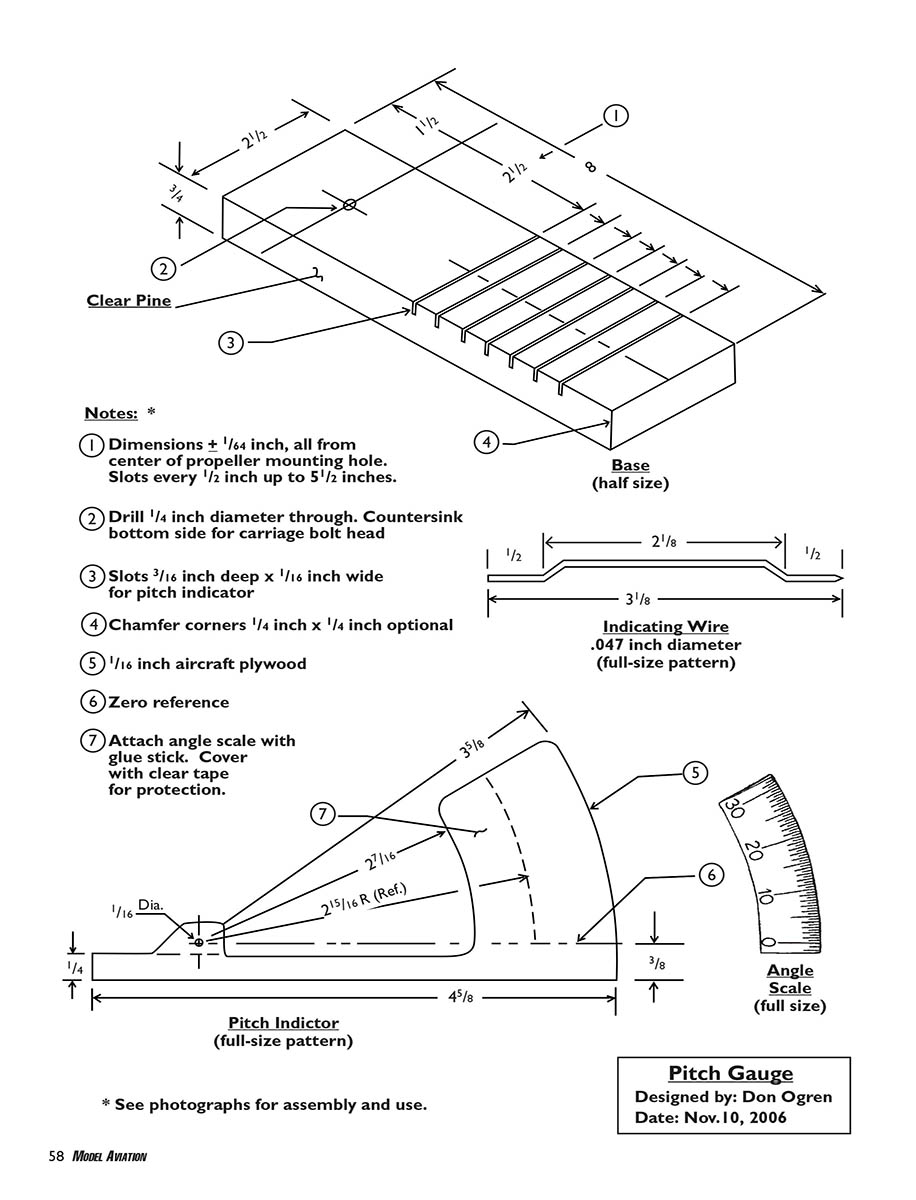
- Materials called out: Clear pine base (half-size pattern), indicating wire 0.047-inch diameter (full-size pattern), pitch indicator (full-size pattern), angle scale (full size).
Notes
- Dimensions ± 1/64 inch, all from center of propeller mounting hole. Slots every 1/2 inch up to 5-1/2 inches.
- Drill 1/4-inch diameter through. Countersink bottom side for carriage bolt head.
- Slots 3/16 inch deep x 1/16 inch wide for pitch indicator.
- Chamfer corners 1/4 inch x 1/4 inch optional.
- 1/16-inch aircraft plywood for the indicator.
- Zero reference.
- Attach angle scale with glue stick. Cover with clear tape for protection.
*See photographs for assembly and use.*
Pitch chart
- X-axis: Blade angle in degrees (0, 5, 10, 15, 20, 25, 30).
- Y-axis: Blade pitch in inches (2 through 13).
- Graphed lines: one line for each blade station—2.0", 2.5", 3.0", 3.5", 4.0", 4.5", 5.0", 5.5".
DHO 12/20/06 Designed by: Don Ogren Date: Nov. 10, 2006
Transcribed from original scans by AI. Minor OCR errors may remain.

