
Build a Servo Chatter Buster
With the myriad electronic devices available to the modeling community, I thought I could purchase anything I might need from one of the many companies that supply these items. However, a requirement for a new device arose when I was completing installation of spoilers on an original-design glider. Each spoiler was controlled with its own servo, and both connected to a single channel with a Y connector. Mechanical adjustments, in addition to transmitter servo-travel programming, resulted in reasonable spoiler operation, but one would always close right before the other.
Programming for more travel resulted in at least one servo chattering as it tried to go beyond the spoiler's mechanical limit. One would not want this condition to exist throughout an entire glider flight because of its continuous current drain on the radio battery. However, I noticed that if the receiver was turned off when the spoilers were fully closed, the chattering stopped (as would be expected) and the spoilers remained in their fully closed position. Necessity being the mother of invention, I conceived an electronic unit that would turn off the servo pulses after a short time period when the servo was near its end position corresponding to the fully closed spoiler condition. The servo would instantly come back to life when the servo channel signal changed.
Such a device is useful only where there is no holding force required (other than the servo's mechanical resistance) to maintain the end-of-travel position. Other applications include cases where a mechanical stop prevents full servo travel, as can occur with throttle operation, flaps in their retracted positions, and functional scale features such as movable canopies, hatches, and bomb bay doors. In these cases, if not precisely adjusted, the servo could be trying to move against a stop and drawing current from the flight pack during most of the flight.
Description
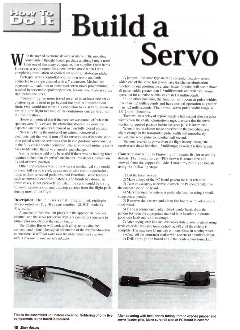
- The unit uses a small, programmed eight-pin microcontroller (PIC12C508).
- A connector from the unit plugs into the appropriate receiver channel, and the servo (or servos with a Y connector) connects to output pins mounted on the circuit board.
- The Chatter Buster works with all systems using the conventional negative-positive-signal orientation of receiver-to-servo connections. It will not work with older Airtronics systems unless you use an appropriate adapter.
- A jumper (the same type used on computer boards) selects which end of the servo travel will have the chatter-elimination function:
- In one jumper position, the chatter-buster function will occur for pulse widths greater than about 1.8 milliseconds; normal operation occurs for pulse widths less than 1.8 ms.
- In the other position, the function will occur for pulse widths less than about 1.2 milliseconds; normal operation occurs for pulse widths greater than 1.2 ms.
- The normal servo pulse-width range is approximately 1.0–2.0 ms.
- There is a delay of approximately 0.5 second after the pulse width enters the chatter-elimination range, to ensure the servo reaches its required position before the servo pulse is interrupted.
- While in the no-chatter range, any slight change in the transmitted pulse width will immediately reactivate the servo pulse for another 0.5 second.
- The unit receives power from the flight battery through the receiver, draws less than 1.5 mA, and weighs about 3 grams.
Construction
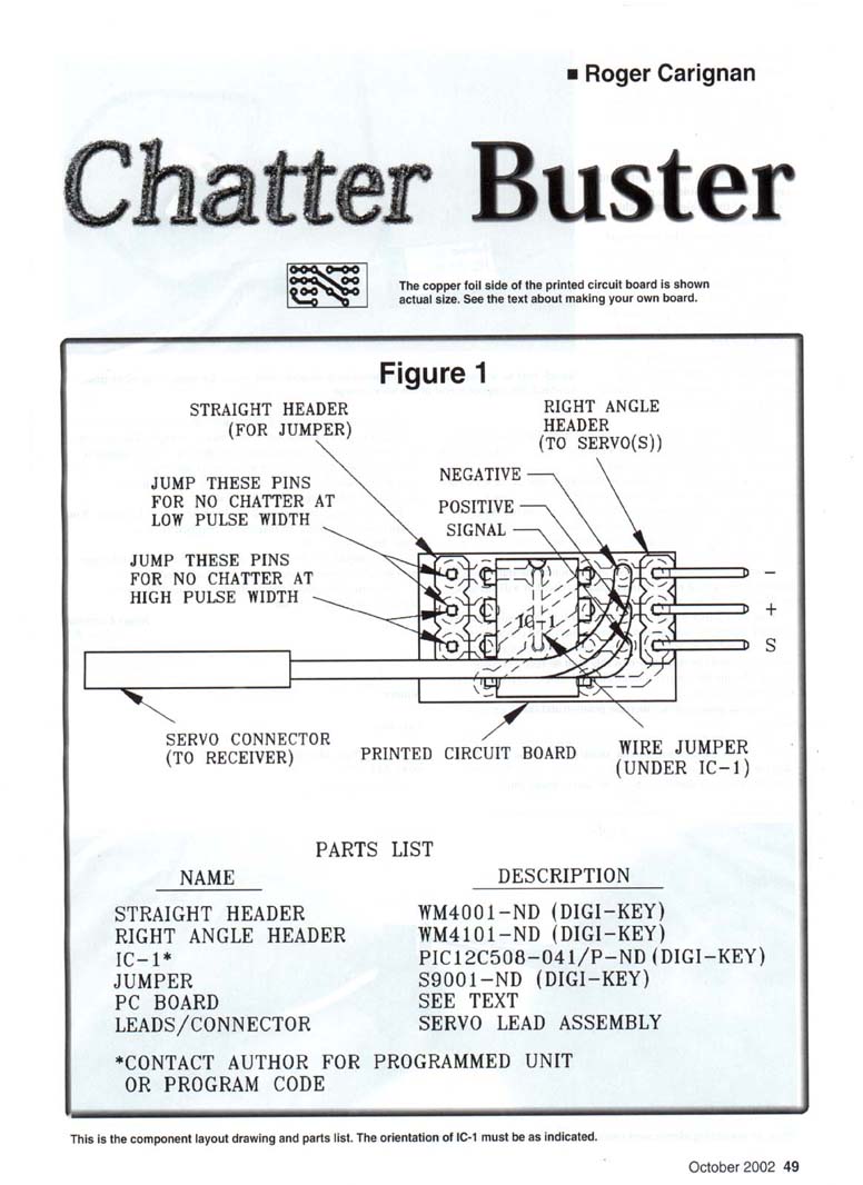
Refer to Figure 1 and the parts list for assembly details. The printed circuit (PC) shown in Figure 1 is actual size and viewed from the copper-foil side.
If you make your own prototype PC boards, use these steps:
- Cut the board to size.
- Make a copy of the PC-board pattern for later reference.
- Tape or use spray adhesive to attach the PC-board pattern to the copper side of the board.
- Mark through the pattern at each hole location using a small, sharp center punch.
- Remove the pattern and clean the board with solvent and steel wool.
- Using a permanent marker (black works best), draw the pattern between the appropriate marked hole locations to ensure good-size lands and solid coverage.
- After drying, etch in a shallow cup or dish (plastic or glass) using ferric chloride until the etching is complete. This may take 15 minutes or more. Rinse in running water.
- Clean off the permanent marker with acetone or a similar solvent.
- Drill through the board at all the center-punch-marked locations.
The copper-foil side of the printed circuit board is shown actual size in Figure 1.
Figure 1 component/connector notes:
- Straight header (for jumper)
- Right-angle header (to servo(s))
- Jump these pins for no chatter at low pulse width
- Jump these pins for no chatter at high pulse width
- Servo connector (to receiver)
- Printed circuit board
- Wire jumper (under IC-1)
- Pin markings: - - + S (negative, negative, positive, signal)
Parts List
- STRAIGHT HEADER — WM4001-ND (Digi-Key)
- RIGHT-ANGLE HEADER — WM4101-ND (Digi-Key)
- IC-1* — PIC12C508-04/P-ND (Digi-Key)
- JUMPER — S9001-ND (Digi-Key)
- PC BOARD — see text (or contact author for a commercially made board)
- LEADS / CONNECTOR — servo lead assembly
*Contact author for programmed unit or program code.
This is the component layout and parts list. The orientation of IC-1 must be as indicated on the layout. If you do not want to make your own board, contact the author for one that is commercially made.
Assembly and Installation
- Solder a small, solid wire jumper and the two three-pin headers into position as shown in the component-layout drawing. Note the proper location of the straight and right-angle headers.
- The microcontroller (IC-1) is a programmed unit. If you or someone you know can program these, contact the author to receive the code file necessary to program the IC. Contact the author for programmed units if needed.
- Properly orient IC-1 on the board using the notch/half-round index mark as shown in the drawing. Solder all eight pins to the circuit-board lands.
- Solder the three servo-connector wires from the servo connector to the three positions shown. Verify the proper polarity as indicated (negative, positive, signal).
- Check the solder connections on the copper side of the board and make sure there are no solder bridges between traces.
- Place the jumper in one of the two positions on the straight header. Warning: do not inadvertently place the jumper over the two +/- pins of the right-angle header; this would short the battery when plugged in.
- Connect a servo with the proper orientation to the right-angle header. If connected with the orientation reversed, it will not operate but will not cause damage.
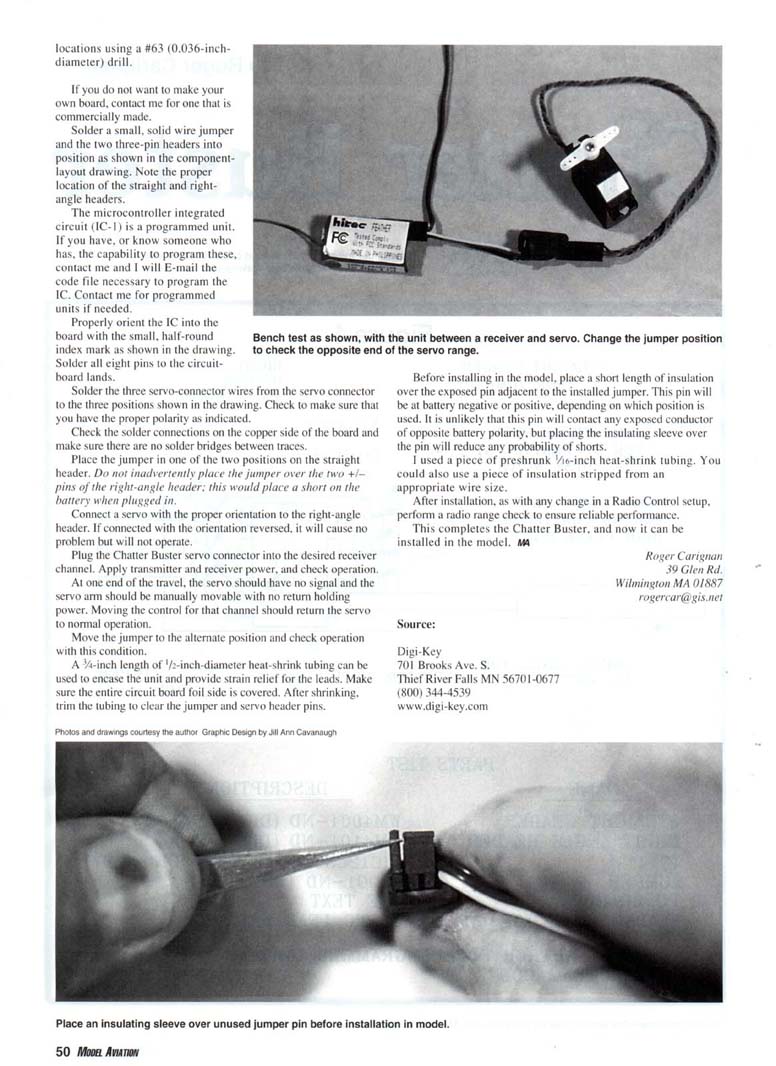
- Plug the Chatter Buster servo connector into the desired receiver channel. Apply transmitter and receiver power, and check operation.
- At the chatter-elimination end of travel, the servo should have no signal and the servo arm should be manually movable with no holding force.
- Moving the control for that channel should immediately return the servo to normal operation.
- Move the jumper to the alternate position and check operation for that condition as well.
Enclosure and strain relief:
- A 3/4-inch length of 1/16-inch-diameter heat-shrink tubing can be used to encase the unit and provide strain relief for the leads. Make sure the entire circuit-board foil side is covered. After shrinking, trim the tubing to clear the jumper and servo header pins.
- Before installing in the model, place a short length of insulation over the exposed pin adjacent to the installed jumper. That pin will be at battery negative or positive, depending on which position is used. Although it is unlikely this pin will contact any exposed conductor of opposite polarity, the insulating sleeve reduces the probability of shorts.
- I used a piece of preshrunk 1/16-inch heat-shrink tubing. You could also use a piece of insulation stripped from an appropriate wire size.
Final checks:
- After installation, as with any change in an R/C setup, perform a radio range check to ensure reliable performance.
This completes the Chatter Buster; it is now ready for installation in the model.
Roger Carignan 39 Glen Rd. Wilmington, MA 01887 [email protected]
Source (parts supplier): Digi-Key 701 Brooks Ave. S. Thief River Falls, MN 56701-0677 (800) 344-4539 www.digi-key.com
Photos and drawings courtesy the author. Graphic design by Jill Ann Cavanaugh.
Transcribed from original scans by AI. Minor OCR errors may remain.

