
Building From Scratch
We are getting close to a wrap for my portion of the "From the Ground Up" series. In the past eight months you have learned about radio-control (RC) systems, electric-power systems, assembling an Almost Ready-to-Fly (ARF) model, flying that model, and last month you learned the A to Z of batteries.
The next step could have gone in either of two directions: building a model from a kit or building a model from raw materials—from scratch. I chose the latter and came up with a new RC trainer design that I call the "Scratch-One." The idea was to utilize the RC system and the electric power system from the Aero Craft Pogo ARF. The Scratch-One RC trainer design is slightly larger and slightly heavier than the Pogo. Specifically, the wing area is 247 square inches, the wingspan is 45 inches, and the all-up weight is 16.9 ounces (approximately an ounce heavier than the Pogo).
The Scratch-One design can be classified as an RC electric-powered trainer sailplane. It has proven to be one of the most forgiving designs to fly and is perfect for the RC beginner, but keep in mind that the thrust of this article is to get you to build your first model from scratch. The pieces won't be fabricated or preassembled; it is all going to be strictly up to you. As part of the process you will also cover all or part of your model.
Obtaining the necessary balsa, plywood, and spruce pieces to construct this model took at least three visits to local hobby shops; not every hobby dealer will have every stick you need. I thought this might be an initial point of frustration, so I came up with an idea.
Craig Wagner, who owns Aero Craft, agreed to make a box of wood for the Scratch-One. It will have all of the wood material you need, and in the correct sizes. The only things you will have to purchase on your own are the cements, covering material, and hardware such as control rods, control horns, and control-surface hinges. You can reach Craig at:
Aero Craft Ltd. 432 Hallett Ave. Riverhead, NY 11901 Tel.: (631) 369-9319 Web site: www.aerocraftrc.com
Editor's note: Since this article was written, we have received pricing and shipping information from Aero Craft Ltd. for the materials to build the Scratch-One. The "kit" of materials is $19.95 plus $6 shipping and handling. This kit will come packed in a 4 x 4 x 36-inch mailer box.
About the Design
Before I get into the construction, I want to point out some of the Scratch-One's design features. Cutting out wing ribs can be a tedious job, especially for a beginner. So in this design I eliminated all wing ribs and substituted balsa sticks.
The bottom stick is 1/8 x 1/4 balsa. Next come three different-size wing spars, then 1/16 x 1/4 balsa sticks are bent over the spars to provide the necessary airfoil shape. The leading edge is common 3/16-inch-diameter hardwood dowel. You won't likely experience much damage on rough landings with this kind of construction.
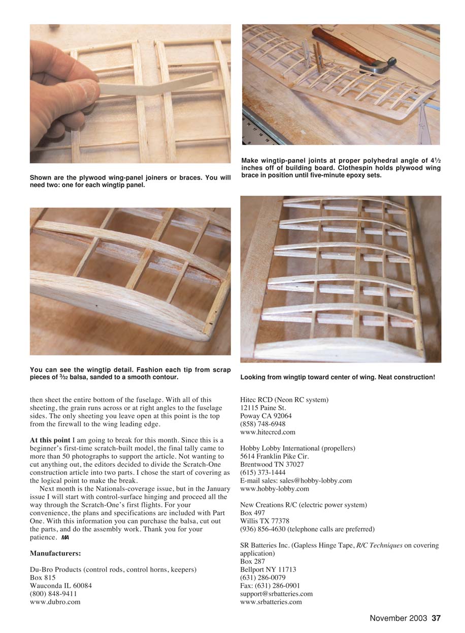
I also made the wing's center section flat so that no center joiner or brace is necessary. Both tips are raised 4 1/2 inches for what we call "polyhedral." These raised tips provide overall stability in flight.
Many models have what I call "internal" battery compartments; to access the battery pack for charging purposes, you must remove the wing. I find that annoying and time-consuming, so in this design the battery compartment is on the bottom of the fuselage where it can be accessed directly without touching the wing.
Probably the most difficult task for the beginner is to mount the servos and hook up the control rods that operate the rudder and elevator. To keep it simple I placed the two servos on top of the fuselage, just aft of the wing trailing edge. It's kind of like "letting it all hang out"!
The control rods are run externally from the servo output arms back to the control horns on the rudder and elevator. This makes for easy control-throw adjustments and easy centering of the controls. These few ideas made the Scratch-One extremely simple to build and fly.
Construction
I like to make my own "kit" of parts before starting the assembly. On this model you must make two fuselage sides and all of the tail pieces from 3/32 balsa. You also have to cut out four fuselage formers from 1/16 plywood and a fifth former from 3/32 balsa. The last items are two 1/16 plywood wing-panel joiners—one for each tip panel.
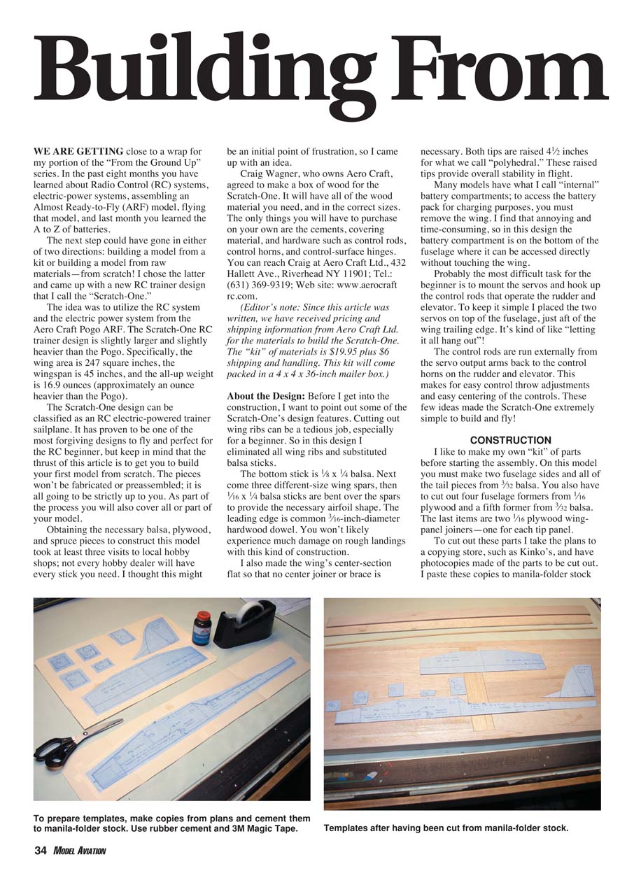
To cut out these parts I take the plans to a copying store, such as Kinko's, and have photocopies made of the parts to be cut out. I paste these copies to manila-folder stock (file folders opened up) using rubber cement and 3M Magic Tape.
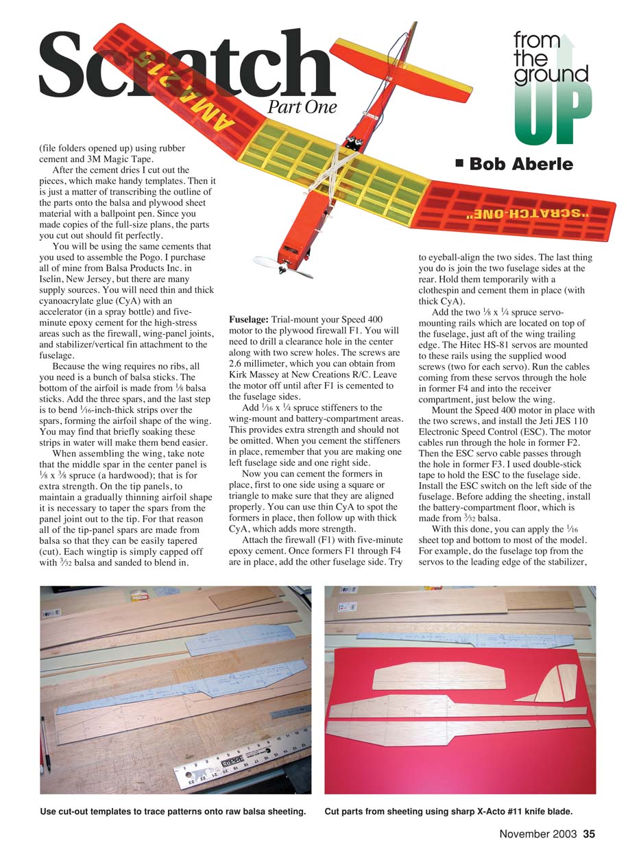
After the cement dries I cut out the pieces, which make handy templates. Then it is just a matter of transcribing the outline of the parts onto the balsa and plywood sheet material with a ballpoint pen. Since you made copies of the full-size plans, the parts you cut out should fit perfectly.
You will be using the same cements that you used to assemble the Pogo. I purchase all of mine from Balsa Products Inc. in Iselin, New Jersey, but there are many supply sources. You will need thin and thick cyanoacrylate glue (CyA) with an accelerator (in a spray bottle) and five-minute epoxy cement for the high-stress areas such as the firewall, wing-panel joints, and stabilizer/vertical fin attachment to the fuselage.
Because the wing requires no ribs, all you need is a bunch of balsa sticks. The bottom of the airfoil is made from 1/8 x 1/4 balsa sticks. Add the three spars, and the last step is to bend 1/16-inch-thick strips over the spars, forming the airfoil shape of the wing. You may find that briefly soaking these strips in water will make them bend easier.
When assembling the wing, take note that the middle spar in the center panel is 1/8 x 3/8 spruce (a hardwood); that is for extra strength. On the tip panels, to maintain a gradually thinning airfoil shape it is necessary to taper the spars from the panel joint out to the tip. For that reason all of the tip-panel spars are made from balsa so that they can be easily tapered (cut). Each wingtip is simply capped off with 3/32 balsa and sanded to blend in.
Fuselage
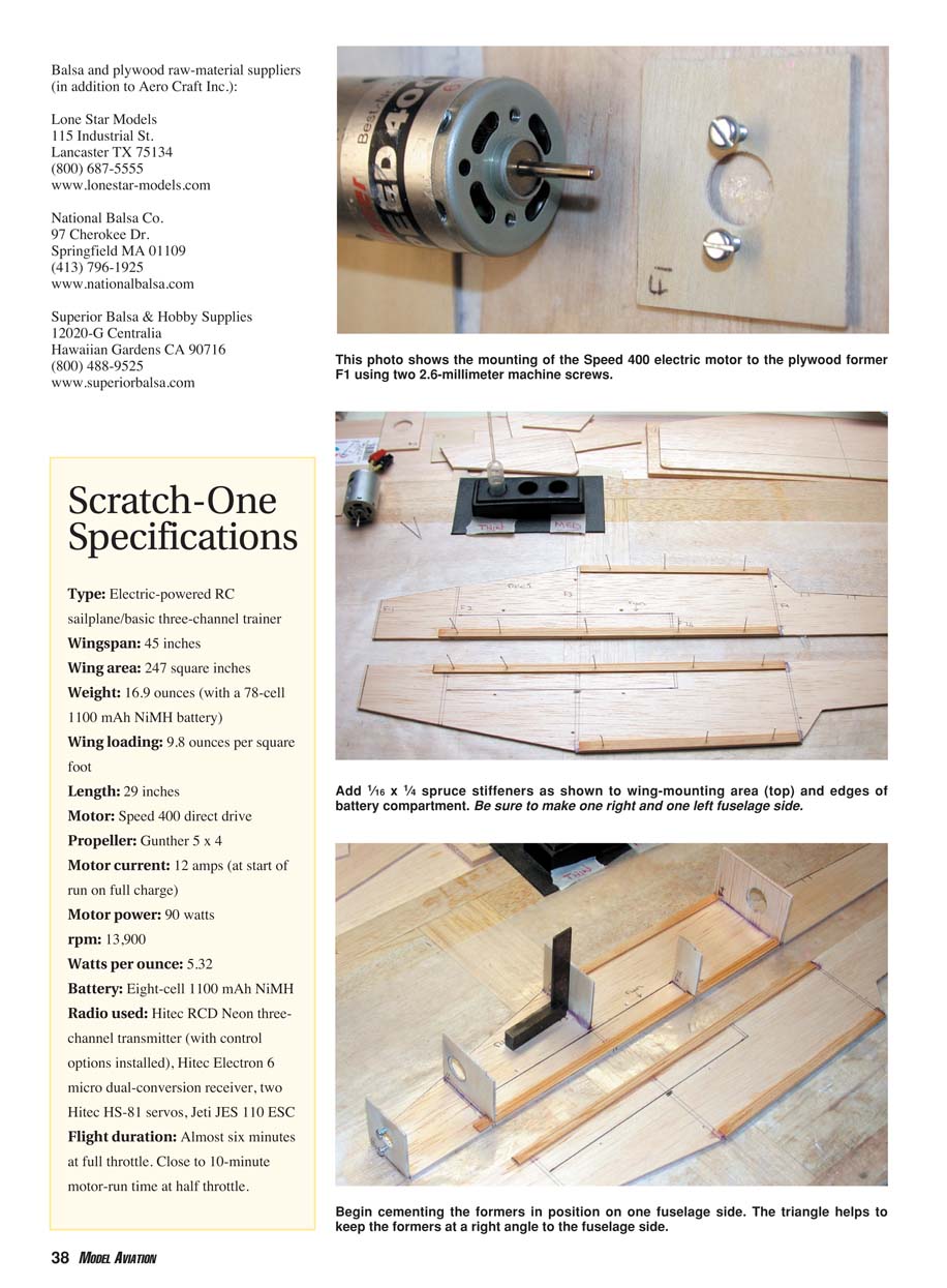
Trial-mount your Speed 400 motor to the plywood firewall F1. You will need to drill a clearance hole in the center along with two screw holes. The screws are 2.6 millimeter, which you can obtain from Kirk Massey at New Creations R/C. Leave the motor off until after F1 is cemented to the fuselage sides.
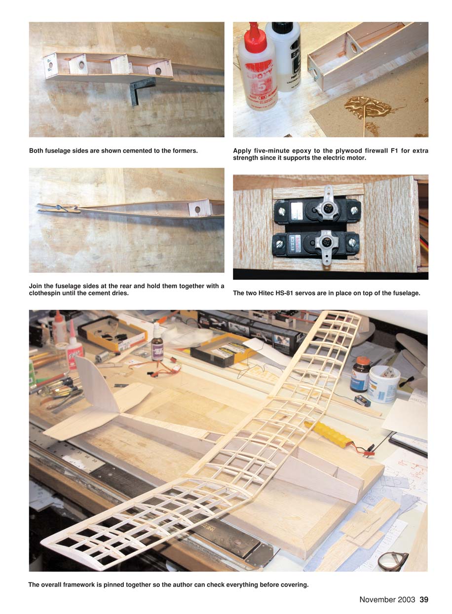
Add 1/16 x 1/4 spruce stiffeners to the wing-mount and battery-compartment areas. This provides extra strength and should not be omitted. When you cement the stiffeners in place, remember that you are making one left fuselage side and one right side.
Now you can cement the formers in place, first to one side using a square or triangle to make sure that they are aligned properly. You can use thin CyA to spot the formers in place, then follow up with thick CyA, which adds more strength.
Attach the firewall (F1) with five-minute epoxy cement. Once formers F1 through F4 are in place, add the other fuselage side. Try to eyeball-align the two sides. The last thing you do is join the two fuselage sides at the rear. Hold them temporarily with a clothespin and cement them in place (with thick CyA).
Add the two 1/8 x 1/4 spruce servo-mounting rails which are located on top of the fuselage, just aft of the wing trailing edge. The Hitec HS-81 servos are mounted to these rails using the supplied wood screws (two for each servo). Run the cables coming from these servos through the hole in former F4 and into the receiver compartment, just below the wing.
Mount the Speed 400 motor in place with the two screws, and install the Jeti JES 110 electronic speed control (ESC). The motor cables run through the hole in former F2. Then the ESC servo cable passes through the hole in former F3. I used double-stick tape to hold the ESC to the fuselage side. Install the ESC switch on the left side of the fuselage. Before adding the sheeting, install the battery-compartment floor, which is made from 3/32 balsa.
With this done, you can apply the 1/16-inch sheeting top and bottom to most of the model. For example, do the fuselage top from the servos to the leading edge of the stabilizer, and the bottom from the servos back to the tail. For the nose area cut a paper template and trace it onto the 1/16-inch sheeting. Cut out the nose pieces and fit them into place. Add the cowl piece, which is made from 3/32-inch balsa, and sand to shape.
The tailgroup (stabilizer and fin) is assembled on the building board. Use straightedges and squares to ensure that the pieces are properly aligned. Install the control horns in the elevator and rudder; use small 2-56 bolts or nylon pushrods for the linkage. Cover the model with your choice of covering film. I used Solarfilm. Balance the model by adding small amounts of weight in the nose or tail until you achieve the correct center of gravity, which is specified on the plans.
Before your first flight, check all controls for proper direction and throw. Triple-check the motor and battery polarity and the ESC programming. Do a range check on your radio gear. For the first flights, use calm conditions and hand-launch the model or use a gentle belly-launch from a small hill. Make small trim adjustments as needed.
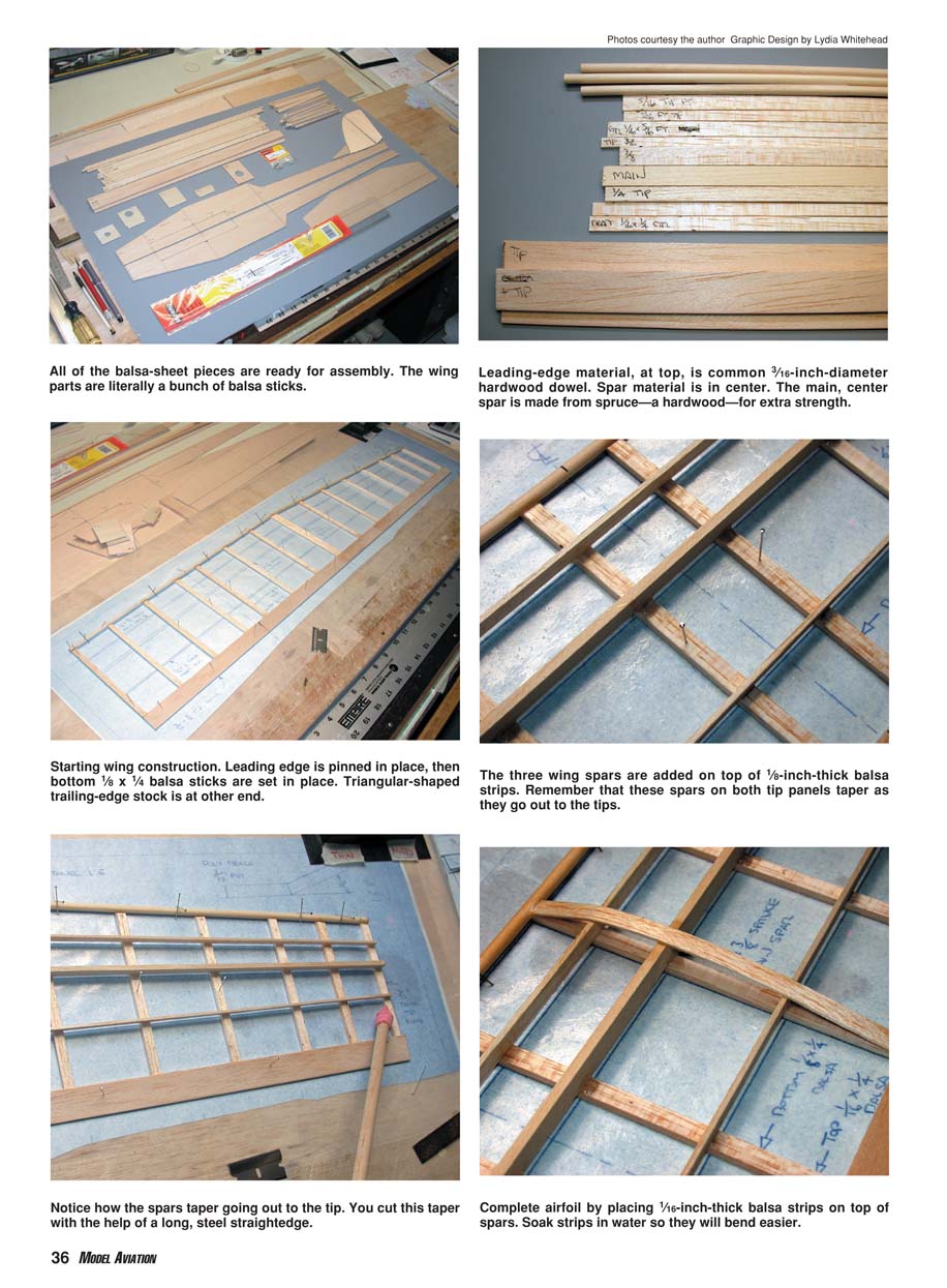
All of the balsa-sheet pieces are ready for assembly. The wing parts are literally a bunch of balsa sticks. The leading-edge material, at top, is common 3/16-inch-diameter hardwood dowel. The main, center spar is made from spruce—a hardwood—for extra strength.
Starting wing construction: leading edge is pinned in place, then bottom 1/8 x 1/4 balsa sticks are set in place. Triangular-shaped trailing-edge stock is at the other end.
The three wing spars are added on top of 1/8-inch-thick balsa strips. Remember that these spars on both tip panels taper as they go out to the tips. You cut this taper with the help of a long, steel straightedge.
Complete the airfoil by placing 1/16-inch-thick balsa strips on top of the spars. Soak strips in water so they will bend easier.
Then sheet the entire bottom of the fuselage. With all of this sheeting, the grain runs across or at right angles to the fuselage sides. The only sheeting you leave open at this point is the top from the firewall to the wing leading edge.
At this point I am going to break for this month. Since this is a beginner's first-time scratch-built model, the final tally came to more than 50 photographs to support the article. Not wanting to cut anything out, the editors decided to divide the Scratch-One construction article into two parts. I chose the start of covering as the logical point to make the break.
Next month is the Nationals-coverage issue, but in the January issue I will start with control-surface hinging and proceed all the way through the Scratch-One's first flights. For your convenience, the plans and specifications are included with Part One. With this information you can purchase the balsa, cut out the parts, and do the assembly work. Thank you for your patience. —MA
Both fuselage sides are shown cemented to the formers. Apply five-minute epoxy to the plywood firewall F1 for extra strength since it supports the electric motor. Join the fuselage sides at the rear and hold them together with a clothespin until the cement dries. The two Hitec HS-81 servos are in place on top of the fuselage. The overall framework is pinned together so the author can check everything before covering.
Manufacturers
- Du-Bro Products (control rods, control horns, keepers)
Box 815 Wauconda, IL 60084 (800) 848-9411 www.dubro.com
- Hitec RCD (Neon RC system)
12115 Paine St. Poway, CA 92064 (858) 748-6948 www.hitecrcd.com
- Hobby Lobby International (propellers)
5614 Franklin Pike Cir. Brentwood, TN 37027 (615) 373-1444 E-mail: [email protected] www.hobby-lobby.com
- New Creations R/C (electric power system)
Box 497 Willis, TX 77378 (936) 856-4630 (telephone calls preferred)
- SR Batteries Inc. (Gapless Hinge Tape, R/C Techniques on covering application)
Box 287 Bellport, NY 11713 (631) 286-0079 Fax: (631) 286-0901 [email protected] www.srbatteries.com
Balsa and plywood raw-material suppliers (in addition to Aero Craft Inc.)
- Lone Star Models
115 Industrial St. Lancaster, TX 75134 (800) 687-5555 www.lonestar-models.com
- National Balsa Co.
97 Cherokee Dr. Springfield, MA 01109 (413) 796-1925 www.nationalbalsa.com
- Superior Balsa & Hobby Supplies
12020-G Centralia Hawaiian Gardens, CA 90716 (800) 488-9525 www.superiorbalsa.com
Scratch-One Specifications
- Type: Electric-powered RC sailplane / basic three-channel trainer
- Wingspan: 45 inches
- Wing area: 247 square inches
- Weight: 16.9 ounces (with an eight-cell 1100 mAh NiMH battery)
- Wing loading: 9.8 ounces per square foot
- Length: 29 inches
- Motor: Speed 400 direct drive
- Propeller: Gunther 5 x 4
- Motor current: 12 amps (at start of run on full charge)
- Motor power: 90 watts
- RPM: 13,900
- Watts per ounce: 5.32
- Battery: Eight-cell 1100 mAh NiMH
- Radio used: Hitec RCD Neon three-channel transmitter (with control options installed), Hitec Electron 6 micro dual-conversion receiver, two Hitec HS-81 servos, Jeti JES 110 ESC
- Flight duration: Almost six minutes at full throttle; close to 10-minute motor-run time at half throttle
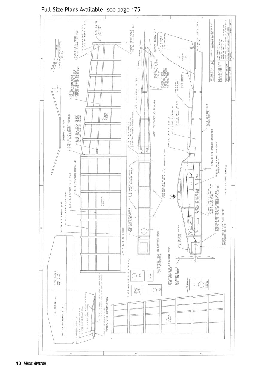
Full-Size Plans Available—see page 175
Transcribed from original scans by AI. Minor OCR errors may remain.

