
Building Separable - 2007/10
Building Separable Wingtips
By Joe Beshar [email protected]
An accurate, hassle-free method of segmenting aircraft components
One of my recent projects has been building a turbine-powered model of a full-scale aircraft that was designed by the Germans and scheduled to be flown in 1946. Construction of the first Messerschmitt P.1112 was halted during World War II by the invasion of US troops in April 1945.
I became interested in the P.1112 when I learned that shortly after the war, its designer, Waldemar Voight, found employment with Chance Vought in the U.S. It is no coincidence that the Navy F7U-1 Cutlass features the P.1112's wing design.
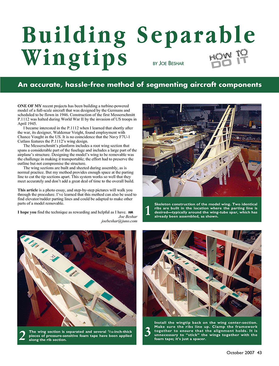
The Messerschmitt's planform includes a root wing section that spans a considerable part of the fuselage and includes a large part of the airplane's structure. Designing the model's wing to be removable was the challenge in making it transportable; the effort had to preserve the outline but not compromise the structure.
The wing sections are built and sheeted during assembly, as is normal practice. My method provides enough space at the parting line to cut the tip sections apart. This system works so well that the parts meet accurately and don't add a great deal of time to the overall build.
This article is a photo essay; step-by-step pictures walk you through the procedure. I've learned that this method can also be used to find elevator/rudder parting lines and could be adapted to make other parts of a model removable.
I hope you find the technique as rewarding and helpful as I have. — Joe Beshar
Tools and materials (typical)
- Balsa sheeting (pre-edge-glued into large sections)
- Clamps and weights
- Slow-curing adhesive or wood glue
- 4-inch length of .045-inch-diameter piano wire
- Dremel-type motor tool
- Steel wool and a cleaner for the wire
- Razor saw
- Softened soap (for lubricating the saw)
- Sanding blocks
Procedure
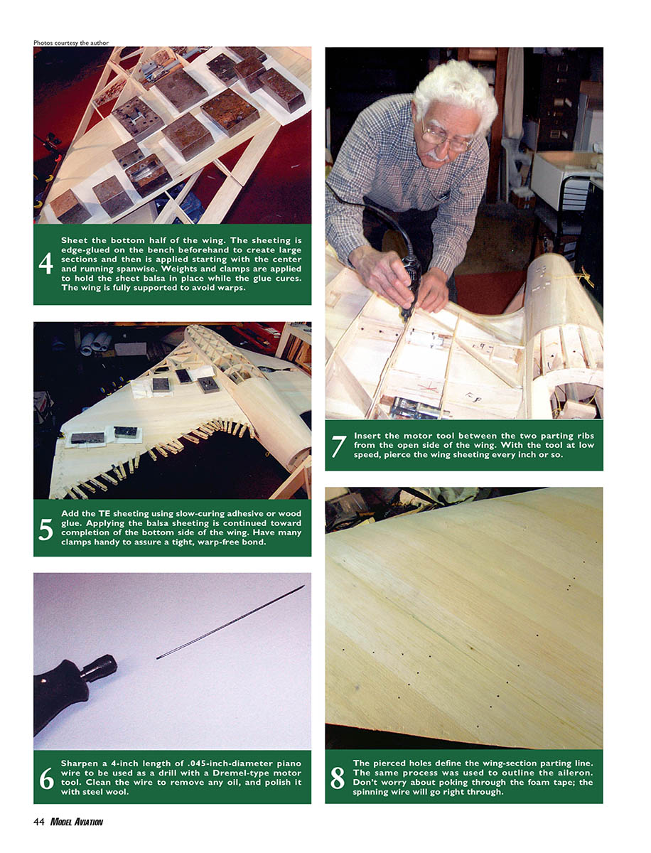
- Sheet the bottom half of the wing.
- Pre-edge-glue the balsa sheeting on the bench to create large sections.
- Apply sheeting starting at the center and running spanwise.
- Use weights and clamps to hold the sheet balsa in place while the glue cures. Fully support the wing to avoid warps.
- Add the trailing-edge (TE) sheeting.
- Use slow-curing adhesive or wood glue.
- Continue applying balsa sheeting until the bottom side of the wing is complete.
- Have many clamps handy to assure a tight, warp-free bond.
- Prepare the drilling wire.
- Sharpen a 4-inch length of .045-inch-diameter piano wire to be used as a drill in the Dremel-type motor tool.
- Clean the wire to remove any oil and polish it with steel wool.
- Perforate the sheeting to mark the parting line.
- After the top side of the wing has been sheeted, insert the motor tool (with the sharpened wire) between the two parting ribs from the open side of the wing.
- With the tool at low speed, pierce the wing sheeting about every inch or so. These pierced holes define the wing-section parting line. The same process can be used to outline the aileron. Don't worry about poking through any foam tape; the spinning wire will go right through.
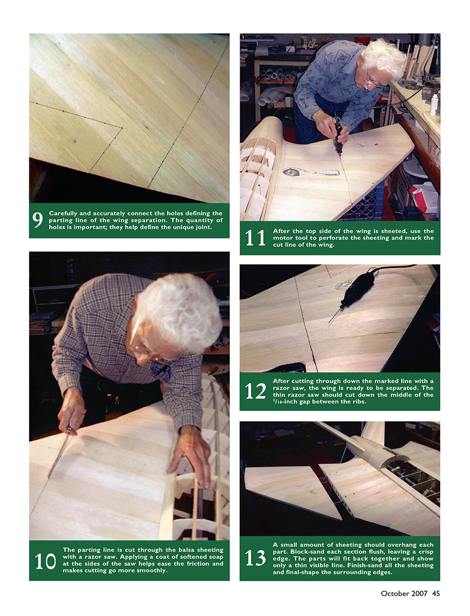
- Connect the perforations and refine the line.
- Carefully and accurately connect the holes to form a continuous parting line for the wing separation. The quantity and spacing of holes are important; they help define the joint.
- Cut the parting line.
- Cut through the balsa sheeting along the marked line using a razor saw.
- Apply a coat of softened soap to the sides of the saw to reduce friction and make cutting smoother.
- The thin razor saw should cut down the middle of the approximately 1/16-inch gap between the ribs.
- Fit and finish the separated parts.
- Leave a small amount of sheeting overhanging each part.
- Block-sand each section flush, leaving a crisp edge. The parts will fit back together and show only a thin visible line.
- Finish-sand all the sheeting and final-shape the surrounding edges.
Notes:
- This method adds only a small amount of work to the build and preserves structural integrity while making the wing removable for transport.
- The same technique can be adapted for other removable control surfaces such as elevators and rudders.
Transcribed from original scans by AI. Minor OCR errors may remain.

