
C-133A Cargomaster
Find out more about the construction of this award-winning model
by George Maiorana and Jay Smith
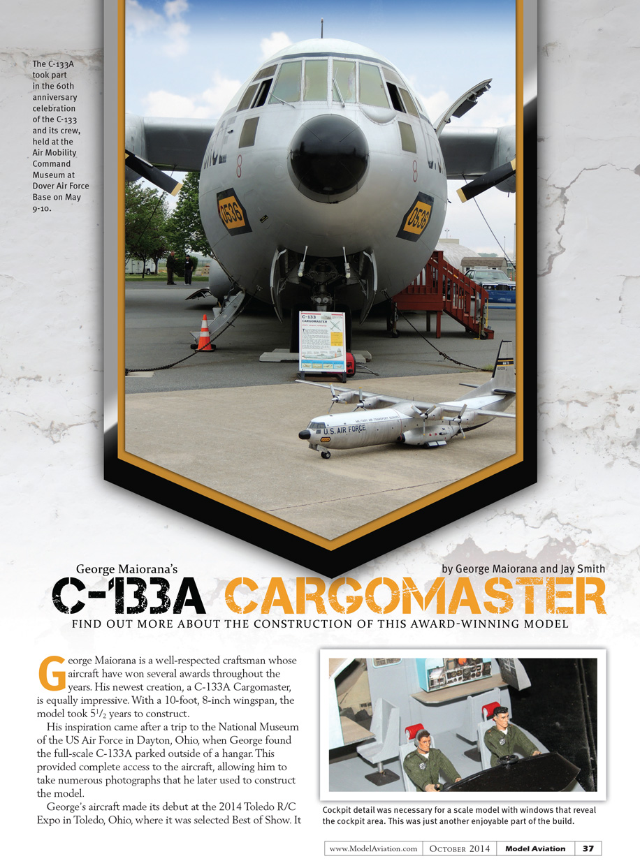
George Maiorana is a well-respected craftsman whose aircraft have won several awards. His newest creation, a C-133A Cargomaster, is equally impressive. The model took 5½ years to construct and has a wingspan of 130.6 inches (approximately 10 ft 10½ in).
George’s inspiration came after a trip to the National Museum of the U.S. Air Force in Dayton, Ohio, where he found a full-scale C-133A parked outside a hangar. Having complete access to the aircraft allowed him to take numerous photographs that he later used to construct the model.
The model made its debut at the 2014 Toledo R/C Expo in Toledo, Ohio, where it was selected Best of Show. It then traveled to Delaware to take part in the 60th anniversary celebration of the C-133 at the Air Mobility Command Museum at Dover Air Force Base on May 9–10.
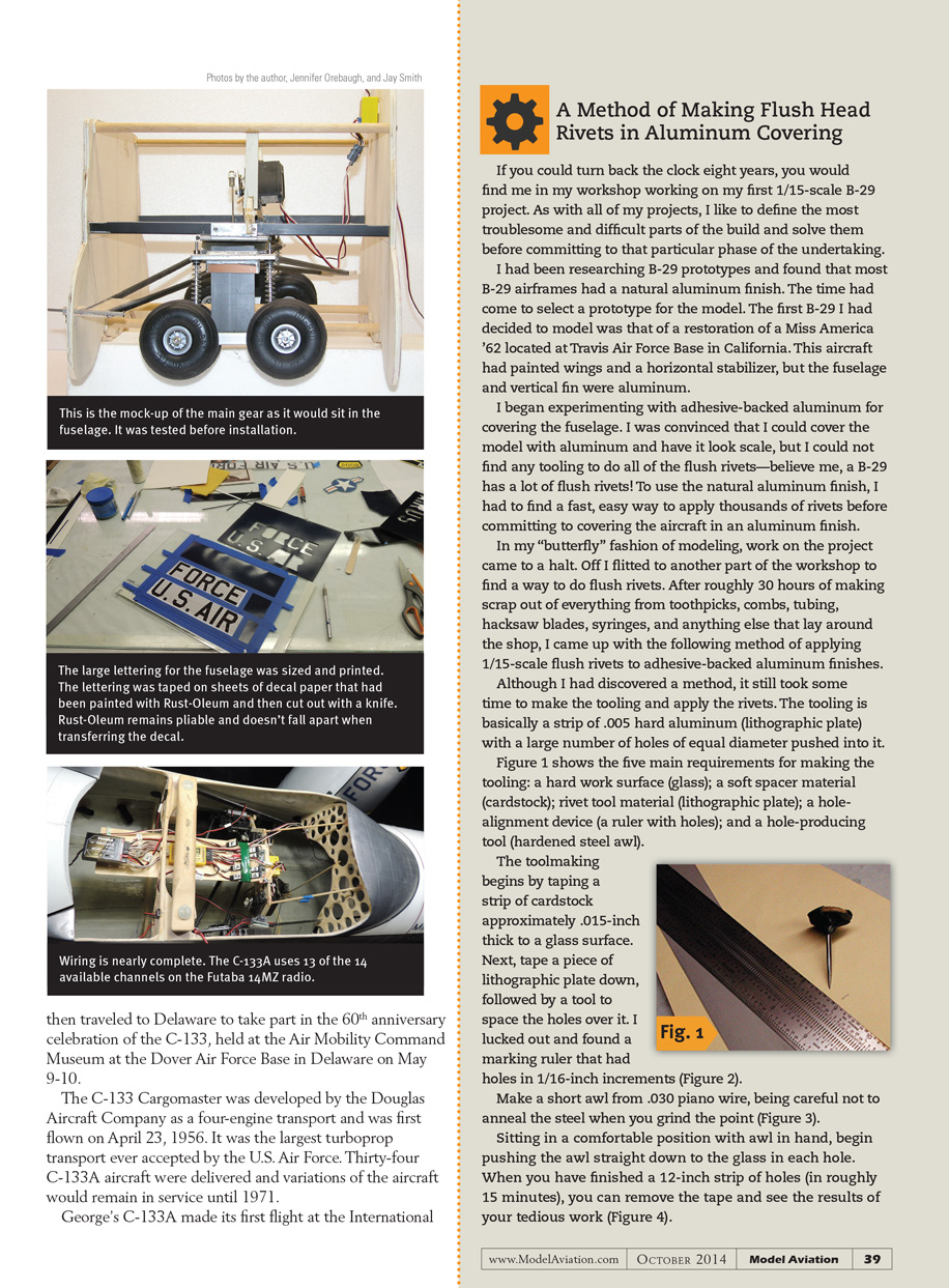
The C-133 Cargomaster was developed by the Douglas Aircraft Company as a four-engine transport and first flew on April 23, 1956. It was the largest turboprop transport ever accepted by the U.S. Air Force. Thirty-four C-133A aircraft were delivered, and variations of the aircraft remained in service until 1971.
Maiden flight and awards
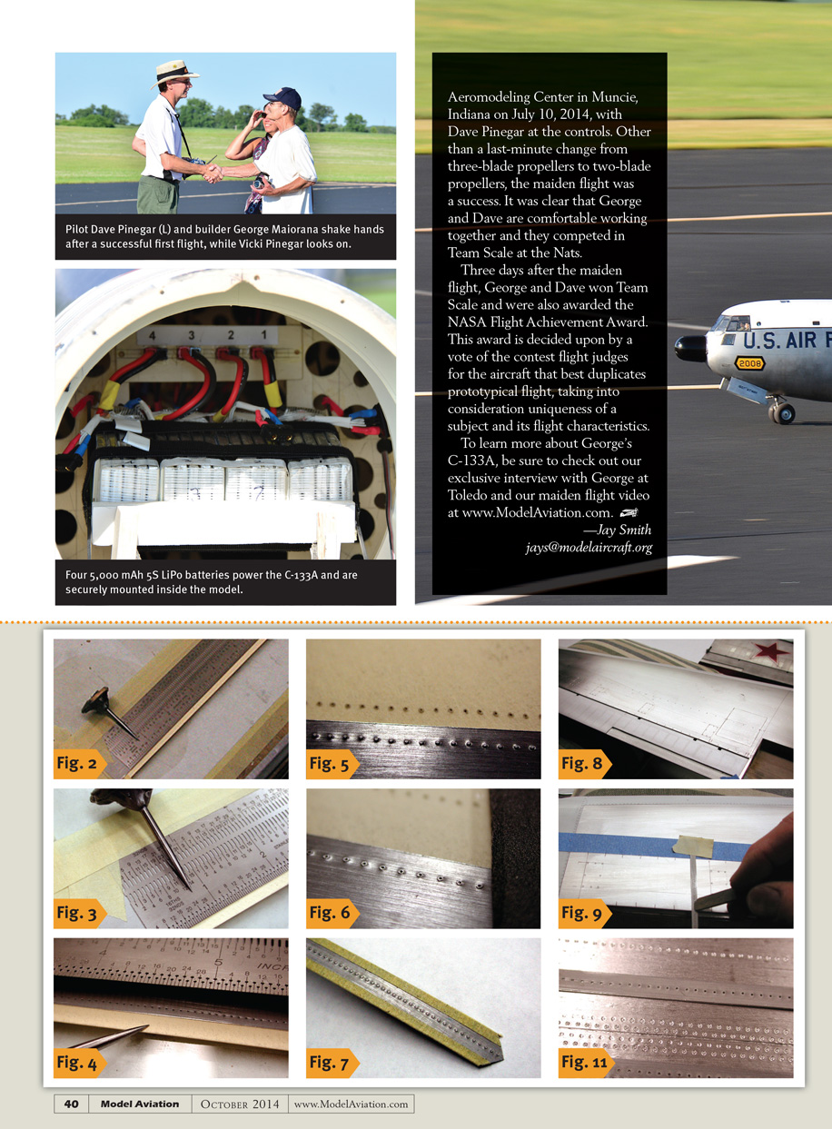
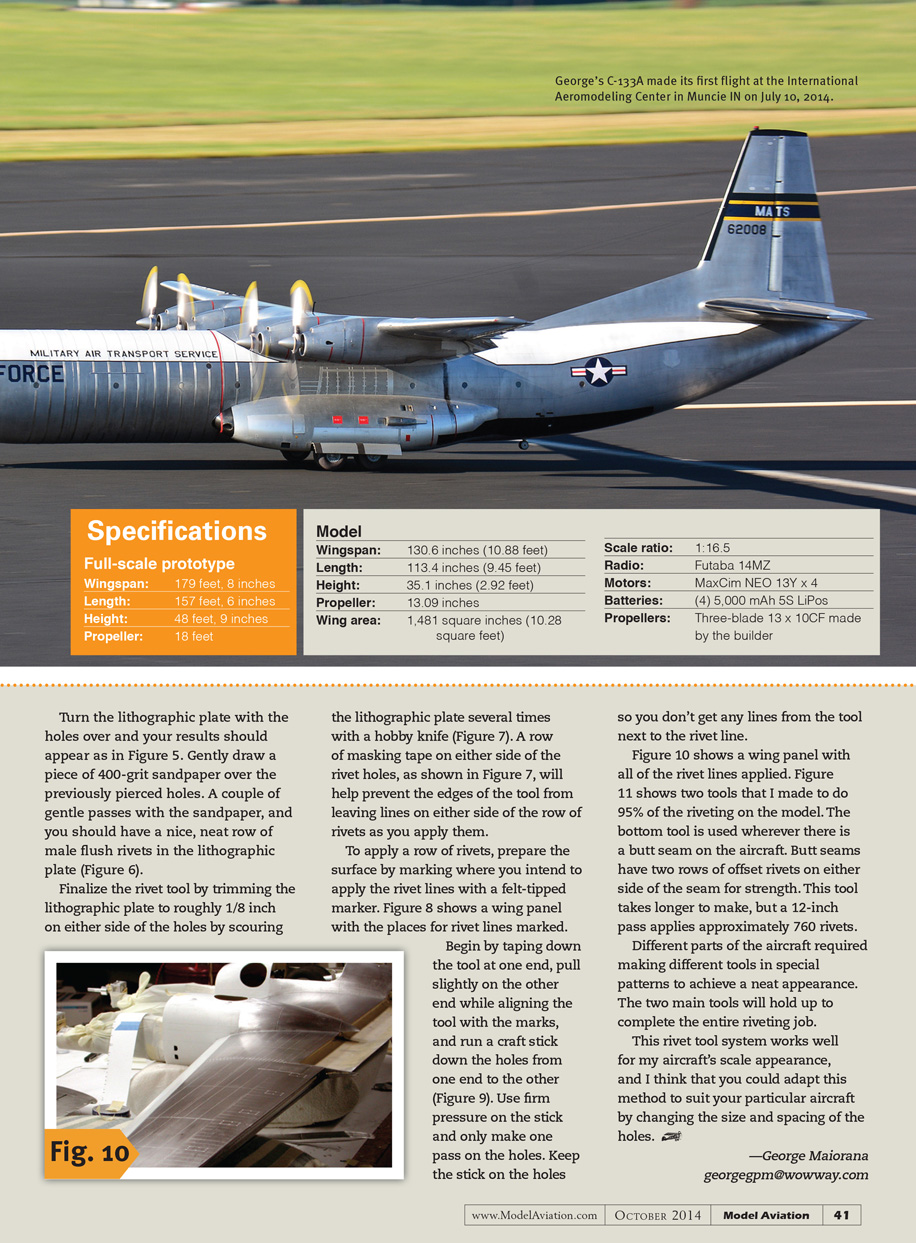
- George’s C-133A made its first flight at the International Aeromodeling Center in Muncie, Indiana, on July 10, 2014, with Dave Pinegar at the controls.
- A last-minute change was made from three-blade propellers to two-blade propellers for the maiden flight; otherwise the flight was uneventful and successful.
- Three days after the maiden flight, George and Dave won Team Scale at the Nats and were awarded the NASA Flight Achievement Award. This award is decided by a vote of the contest flight judges for the subject that best duplicates prototypical flight, taking into consideration uniqueness and flight characteristics.
Construction highlights
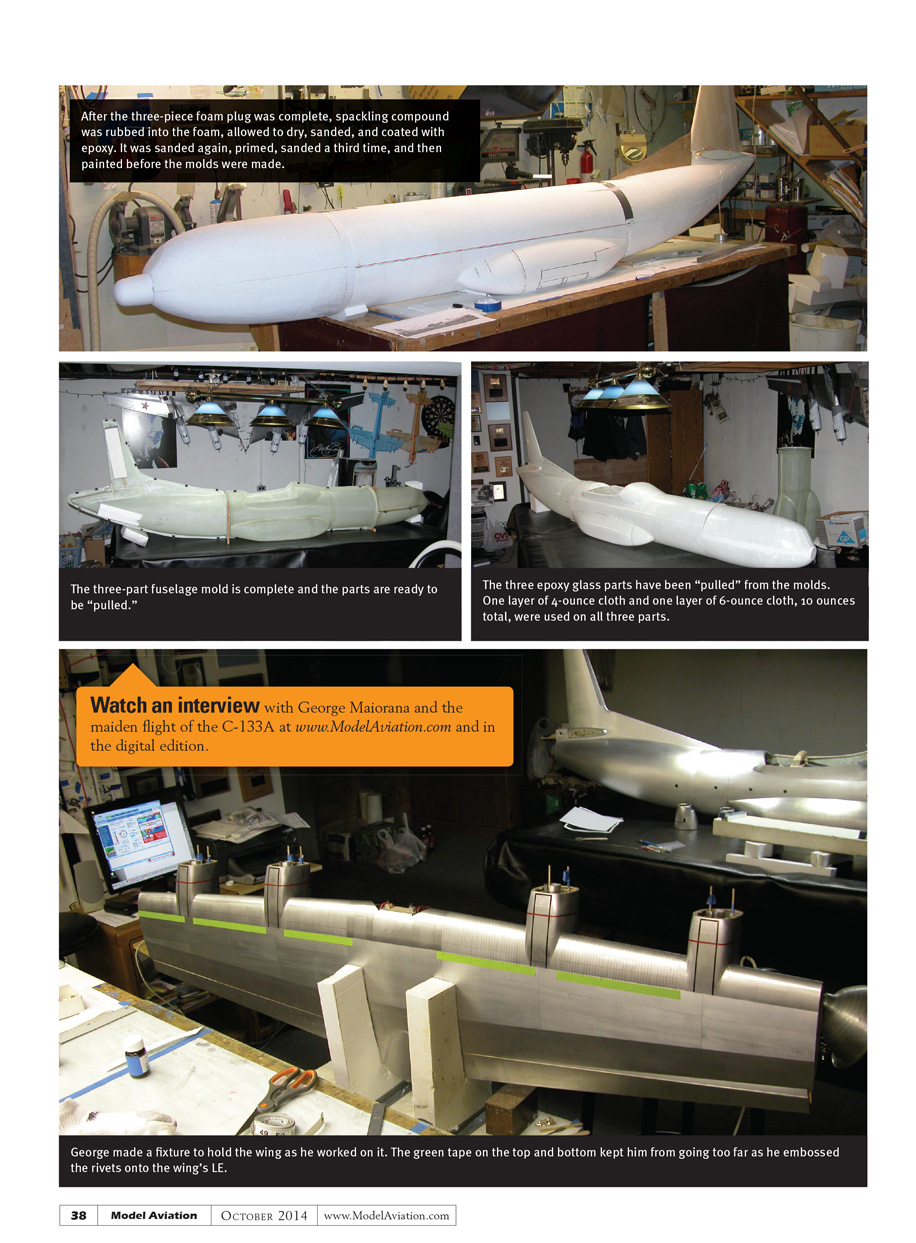
- The build began with a three-piece foam plug. Spackling compound was rubbed into the foam, allowed to dry, sanded, and coated with epoxy.
- The plug was sanded again, primed, sanded a third time, and then painted before molds were made.
- A three-part fuselage mold was created and the parts were pulled from the molds.
- The epoxy-glass parts were laminated with one layer of 4-ounce cloth and one layer of 6-ounce cloth (10 ounces total) on all three parts.
- George made a fixture to hold the wing while working on it. Green tape on the top and bottom guided him as he embossed the rivets onto the wing’s leading edge.
- Watch an interview with George Maiorana and the maiden flight of the C-133A at www.ModelAviation.com and in the digital edition.
—Jay Smith [email protected]
Specifications
Full-scale prototype
- Wingspan: 179 feet, 8 inches
- Length: 157 feet, 6 inches
- Height: 48 feet, 9 inches
- Propeller diameter: 18 feet
Model
- Wingspan: 130.6 inches (approx. 10.88 ft / 10 ft 10½ in)
- Length: 113.4 inches (9.45 ft)
- Height: 35.1 inches (2.92 ft)
- Propeller: 13.09 inches
- Wing area: 1,481 square inches (10.28 square feet)
- Scale ratio: 1:16.5
- Radio: Futaba 14MZ
- Motors: MaxCim NEO 13Y × 4
- Batteries: (4) 5,000 mAh 5S LiPo
- Propellers (builder-made): Three-blade 13 × 10 CF
Transcribed from original scans by AI. Minor OCR errors may remain.

