
CANARROW Sailplane
An Unconventional Two-Meter Canard by Daniel Fritz
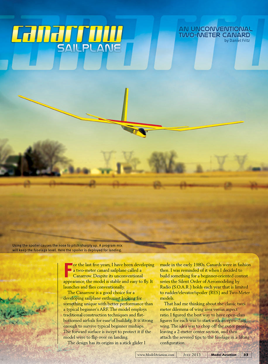
For the last five years I have been developing a two‑meter canard sailplane called the Canarrow. Despite its unconventional appearance, the model is stable and easy to fly. It launches and flies conventionally.
The Canarrow is a good choice for a developing sailplane enthusiast looking for something unique with better performance than a typical beginner ARF. The model employs traditional construction techniques and flat‑bottomed airfoils for ease of building. It is strong enough to survive typical beginner mishaps. The forward surface is swept to protect it if the model were to flip over on landing.
The design has its origins in a stick glider I made in the early 1980s, when canards were in fashion. I was reminded of it when I decided to build something for a beginner‑oriented contest series the Silent Order of Aeromodeling by Radio (S.O.A.R.) holds each year that is limited to rudder/elevator/spoiler (RES) and two‑meter models.
That had me thinking about the classic two‑meter dilemma of wing area versus aspect ratio. I figured the best way to have open‑class figures for each was to start with an open‑class wing. The idea was to chop off the outer panels, leaving a 2‑meter center section, and then attach the severed tips to the fuselage in a lifting configuration.
Technically the Canarrow is a canard because pitch stability and control are provided by a forward lifting surface, but it is more correctly a tandem‑wing airplane. The CG is entirely between the two lifting surfaces. If one were to reassemble the forward wings to the tips of the main wing, the result would span 112 inches, offer 752 square inches of wing area, and have an aspect ratio of roughly 17. Of course, drag is higher (there are twice as many tip vortices); nevertheless, this concept has proven successful.
The tip vortices from the forward wing flow over the top of the main wing at the dihedral breaks where some energy is recaptured. Sweeping the forward wing proved successful in protecting it, as it did on the old stick glider. The forward wing lies behind two lines drawn from the nose to the tips of the main wing.
Assuming the model lands on a flat surface, something else must break before the canard will. The vertical stabilizer is tall enough to protect the canard when the model is inverted.
Construction
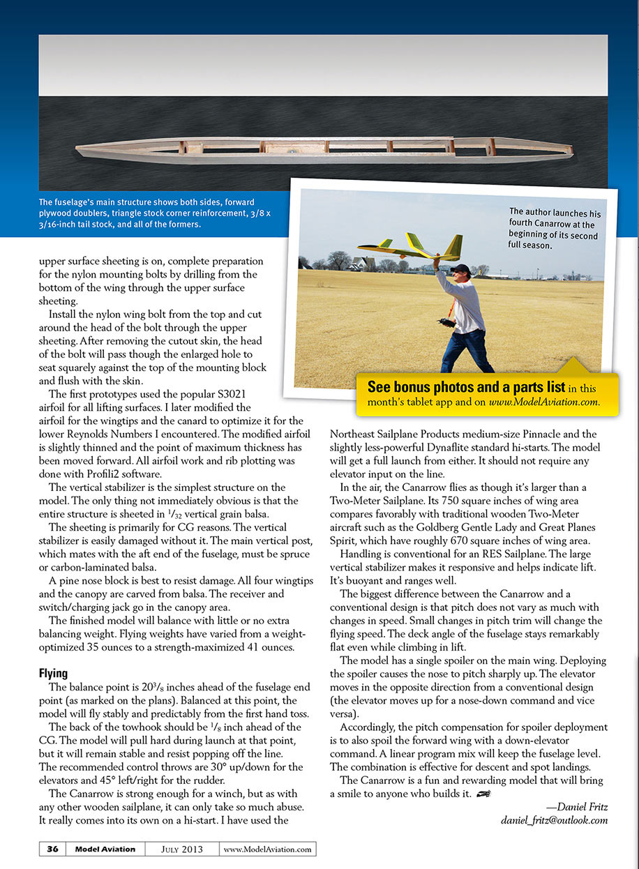
The fuselage is semi‑monocoque: most of its strength comes from a thin 1/16‑inch skin, and the shape is maintained by robust, closely spaced formers. The corner joints are reinforced with triangle‑stock balsa that contributes to the model’s overall strength. It has proven up to the job despite high bending forces during contest landings.
The longest parts on the entire model are the fuselage side panels, which measure 48 inches and can be cut from a single sheet of commercially available balsa. These must be accurately cut to ensure that the wing and canard are properly aligned when everything is finished.
Install the forward plywood doublers by drawing a line 3/16 inch from the nose on the inside of both side panels. Align the tops of the doublers with the tops of each side panel and the front of the doublers with the line. The plywood doublers set the angle of incidence for the canard after removing the excess balsa above them. The triangle‑stock balsa does not extend forward of the plywood doublers. It should also end 3/16 inch from the tail. Cut relief into the upper triangle stock for the doublers.
Glue formers B, C, and all four D's to both sides in a single gluing step using slow‑curing epoxy. Apply clamps or rubber bands around the fuselage sides at each former. Before curing, place the fuselage upside down on the building board and apply weight so the upper surfaces are aligned in the same plane.
The upper sheeting is installed before the lower sheeting to allow the mounting surfaces for the wing and canard to be completed. For CG purposes, the battery and rudder servo are mounted in the aft compartment below the vertical fin.
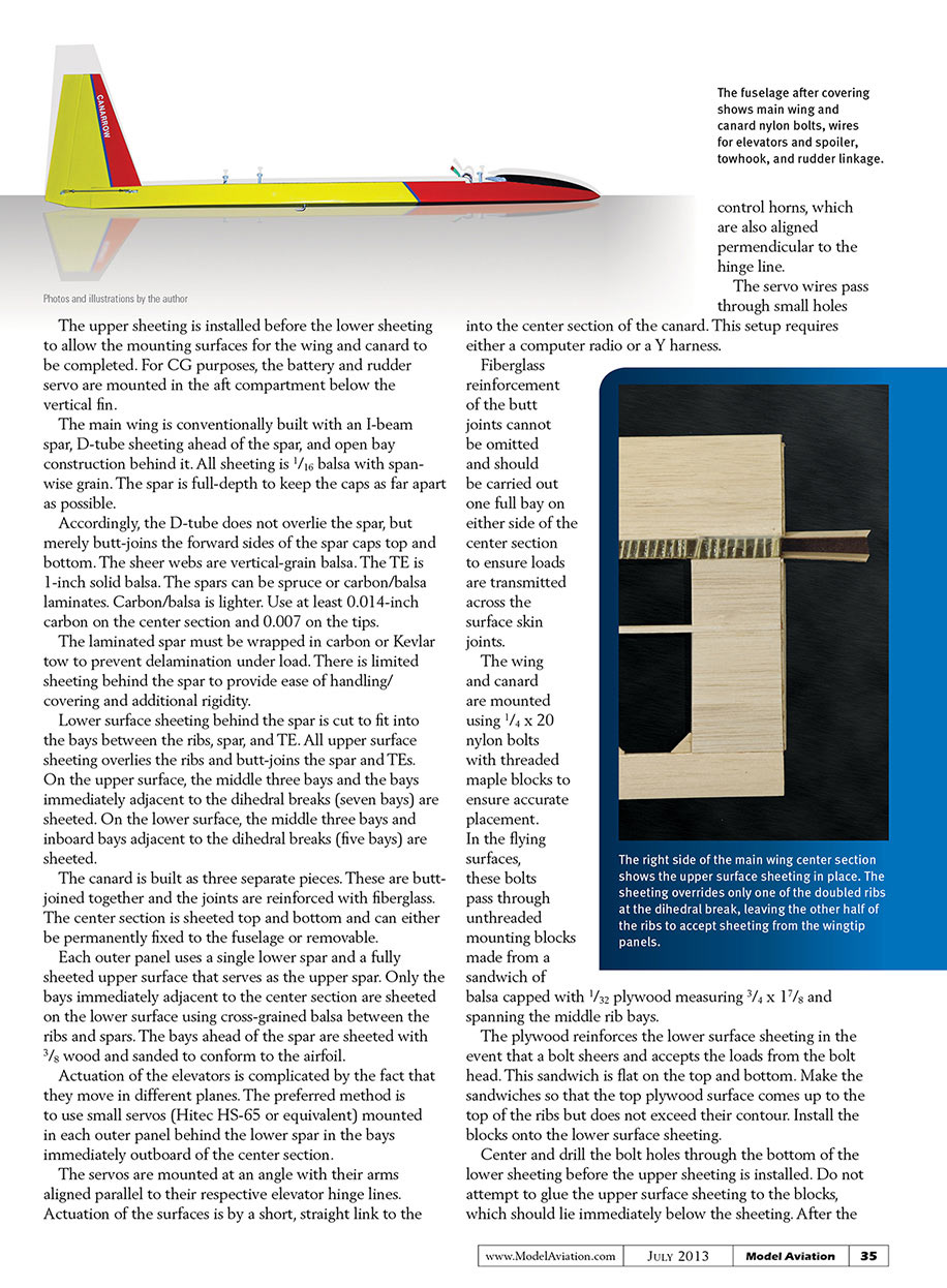
The main wing is conventionally built with an I‑beam spar, D‑tube sheeting ahead of the spar, and open‑bay construction behind it. All sheeting is 1/16‑inch balsa with spanwise grain. The spar is full‑depth to keep the caps as far apart as possible. Accordingly, the D‑tube does not overlie the spar but merely butt‑joins the forward sides of the spar caps top and bottom. The shear webs are vertical‑grain balsa. The trailing edge (TE) is 1‑inch solid balsa. The spars can be spruce or carbon/balsa laminates; carbon/balsa is lighter. Use at least 0.014‑inch carbon on the center section and 0.007‑inch on the tips.
The laminated spar must be wrapped in carbon or Kevlar tow to prevent delamination under load. There is limited sheeting behind the spar to provide ease of handling/covering and additional rigidity. Lower surface sheeting behind the spar is cut to fit into the bays between the ribs, spar, and TE. All upper surface sheeting overlies the ribs and butt‑joins the spar and TEs.
On the upper surface, the middle three bays and the bays immediately adjacent to the dihedral breaks (seven bays total) are sheeted. On the lower surface, the middle three bays and the inboard bays adjacent to the dihedral breaks (five bays total) are sheeted.
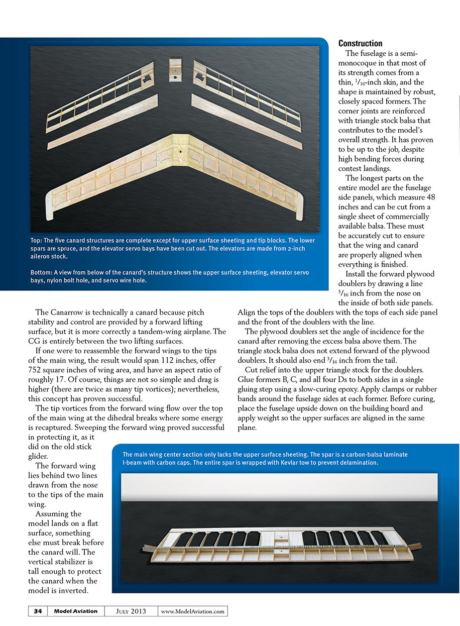
The canard is built as three separate pieces. These are butt‑joined together and the joints are reinforced with fiberglass. The center section is sheeted top and bottom and can either be permanently fixed to the fuselage or removable.
Each outer panel uses a single lower spar and a fully sheeted upper surface that serves as the upper spar. Only the bays immediately adjacent to the center section are sheeted on the lower surface using cross‑grained balsa between the ribs and spars. The bays ahead of the spar are sheeted with 3/32‑inch wood and sanded to conform to the airfoil.
Actuation of the elevators is complicated by the fact that they move in different planes. The preferred method is to use small servos (Hitec HS‑65 or equivalent) mounted in each outer panel behind the lower spar in the bays immediately outboard of the center section. The servos are mounted at an angle with their arms aligned parallel to their respective elevator hinge lines. Actuation of the surfaces is by a short, straight link to the control horns, which are also aligned perpendicular to the hinge line. The servo wires pass through small holes into the center section of the canard. This setup requires either a computer radio or a Y harness.
Fiberglass reinforcement of the butt joints cannot be omitted and should be carried out one full bay on either side of the center section to ensure loads are transmitted across the surface skin joints.
The wing and canard are mounted using 1/4 x 20 nylon bolts with threaded maple blocks to ensure accurate placement. In the flying surfaces, these bolts pass through unthreaded mounting blocks made from a sandwich of balsa capped with 1/32‑inch plywood measuring 3/4 x 1 7/8 inches and spanning the middle rib bays. The plywood reinforces the lower surface sheeting in the event that a bolt shears and accepts the loads from the bolt head. This sandwich is flat on the top and bottom. Make the sandwiches so that the top plywood surface comes up to the top of the ribs but does not exceed their contour. Install the blocks onto the lower surface sheeting.
Center and drill the bolt holes through the bottom of the lower sheeting before the upper sheeting is installed. Do not glue the upper surface sheeting to the blocks; the blocks should lie immediately below the sheeting. After the upper surface sheeting is on, complete preparation for the nylon mounting bolts by drilling from the bottom of the wing through the upper surface sheeting. Install the nylon wing bolt from the top and cut around the head of the bolt through the upper sheeting. After removing the cutout skin, the head of the bolt will pass through the enlarged hole to seat squarely against the top of the mounting block and flush with the skin.
The first prototypes used the popular S3021 airfoil for all lifting surfaces. I later modified the airfoil for the wingtips and the canard to optimize it for the lower Reynolds numbers encountered. The modified airfoil is slightly thinned and the point of maximum thickness has been moved forward. All airfoil work and rib plotting was done with Profili2 software.
The vertical stabilizer is the simplest structure on the model. The entire structure is sheeted in 1/32‑inch vertical‑grain balsa. The sheeting is primarily for CG reasons and to protect the surface from damage. The main vertical post, which mates with the aft end of the fuselage, must be spruce or carbon‑laminated balsa.
A pine nose block is best to resist damage. All four wingtips and the canopy are carved from balsa. The receiver and switch/charging jack go in the canopy area. The finished model will balance with little or no extra balancing weight. Flying weights have varied from a weight‑optimized 35 ounces to a strength‑maximized 41 ounces.
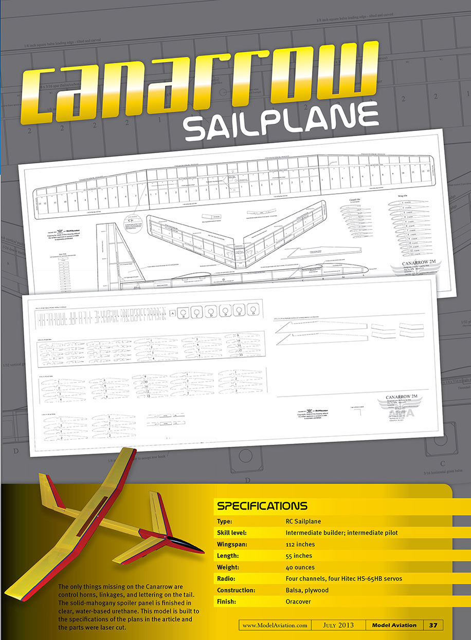
The only things missing on the Canarrow in the pictured model are control horns, linkages, and lettering on the tail. The solid‑mahogany spoiler panel is finished in clear, water‑based urethane. This model is built to the specifications of the plans in the article and the parts were laser cut.
Flying
The balance point is 20 3/8 inches ahead of the fuselage end point (as marked on the plans). Balanced at this point, the model will fly stably and predictably from the first hand toss. The back of the towhook should be 1/8 inch ahead of the CG. The model will pull hard during launch at that point, but it will remain stable and resist popping off the line.
Recommended control throws:
- Elevators: 30° up / 30° down
- Rudder: 45° left / 45° right
The Canarrow is strong enough for a winch, but as with any wooden sailplane, it can only take so much abuse. It really comes into its own on a hi‑start. I have used the Northeast Sailplane Products medium Pinnacle and the slightly less‑powerful Dynaflite standard hi‑starts. The model will get a full launch from either. It should not require any elevator input on the line.
In the air, the Canarrow flies as though it's larger than a two‑meter sailplane. Its approximately 750 square inches of wing area compares favorably with traditional wooden two‑meter aircraft such as the Goldberg Gentle Lady and Great Planes Spirit, which have roughly 670 square inches of wing area.
Handling is conventional for an RES sailplane. The large vertical stabilizer makes it responsive and helps indicate lift. It's buoyant and ranges well. The biggest difference between the Canarrow and a conventional design is that pitch does not vary as much with changes in speed. Small changes in pitch trim will change the flying speed. The deck angle of the fuselage stays remarkably flat even while climbing in lift.
The model has a single spoiler on the main wing. Deploying the spoiler causes the nose to pitch sharply up. The elevator moves in the opposite direction from a conventional design (the elevator moves up for a nose‑down command and vice versa). Accordingly, the pitch compensation for spoiler deployment is to also spoil the forward wing with a down‑elevator command. A linear program mix will keep the fuselage level. The combination is effective for descent and spot landings.
The Canarrow is a fun and rewarding model that will bring a smile to anyone who builds it.
—Daniel Fritz [email protected]
SPECIFICATIONS
- Type: RC sailplane
- Skill level: Intermediate builder; intermediate pilot
- Wingspan: 112 inches
- Length: 55 inches
- Weight: 40 ounces (flight weights have ranged 35–41 oz)
- Radio: Four channels; four Hitec HS‑65HB servos
- Construction: Balsa, plywood (carbon/kevlar reinforcement as noted)
- Finish: Oracover
Transcribed from original scans by AI. Minor OCR errors may remain.

