
The Cardboard Condor
by Ryan Livingston
When I was a much younger kid, I would scrounge up anything I could to build something that resembled an RC model. I’d try to fly most of my creations as gliders, throwing them off hillsides with a cobbled-together radio system for rudder and elevator control. I made wings from foam insulation that I’d cover in packaging tape. Four sheets of balsa for a fuselage and a little more sheeting to make a tail, and I had my next chance at getting something substantial to stay in the air for more than a few seconds. I loved it. The fact that everything I tried to fly usually crashed immediately after the hand launch didn’t stop me from trying again and again.
A few decades later, building and flying come much easier to me. But every now and then I find myself recollecting what a great time of discovery those years were. In hindsight, that’s where the idea to build the Cardboard Condor was born. Now in my 30s, people probably thought I sounded like a 9-year-old a couple years ago when I said, “I’m gonna build a really big RC airplane outta cardboard and pine. And it’s gonna have four engines. And it’ll be really awesome!” They must have thought I was joking. But I was excited by the prospect of trying something new that, as far as I knew, hadn’t been done on such a scale.
The idea of using cardboard came from my school days, when I built an airplane wing cross-section from poster board for use as a visual aid. I was surprised by its rigidity and strength. So the thought of employing some type of cardboard in building a model had been playing in the back of my mind for years.
Designing the Cardboard Condor was mainly a combination of building and design experience, experimenting with materials, and basic formulas for surface area. I designed it with its cardboard covering in mind, using flat surfaces wherever I could. It didn’t have to carry anything but itself. With the wingspan exceeding 12.5 feet, I allowed the fuselage and wings to enjoy a fairly stout build at the cost of a few extra pounds. I never had a multi-engine model before, but over the years I had become comfortable and confident in operating engines, so it didn’t seem like an unwise leap.
Initial estimates of the Condor’s flying weight resulted in a range of 43–53 pounds. That included four 7-inch main wheels at 14 ounces each, four two-stroke O.S. 61FX engines at 23.6 ounces each, and approximately 80 square feet of cardboard, which weighed roughly 10 pounds. Tossing on 6 pounds here and 10 pounds there was unfamiliar territory for me in building RC airplanes. I found myself re-checking the numbers as I built. I estimated the design could absorb this extra weight and still keep the wing loading within an acceptable range.
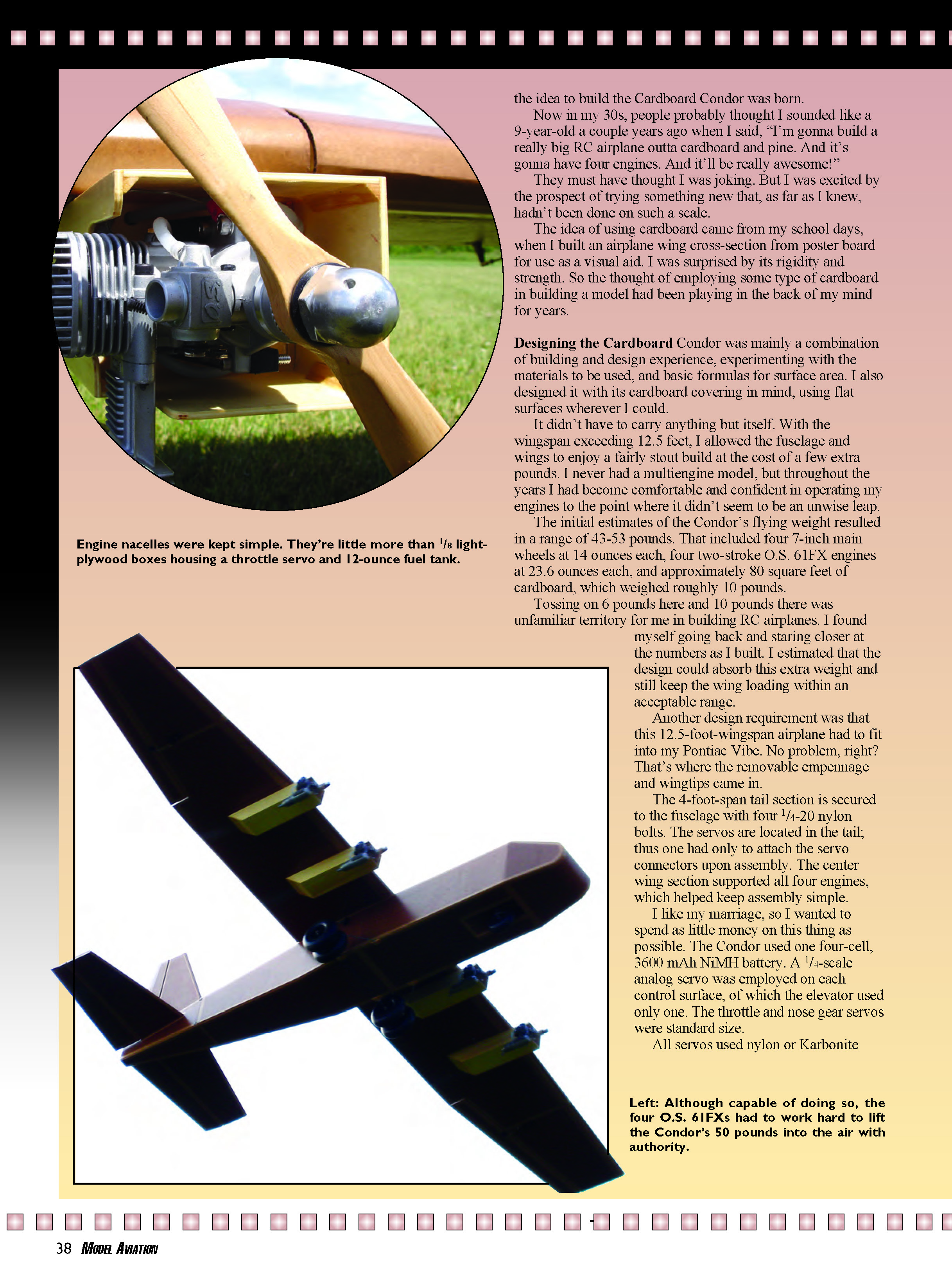
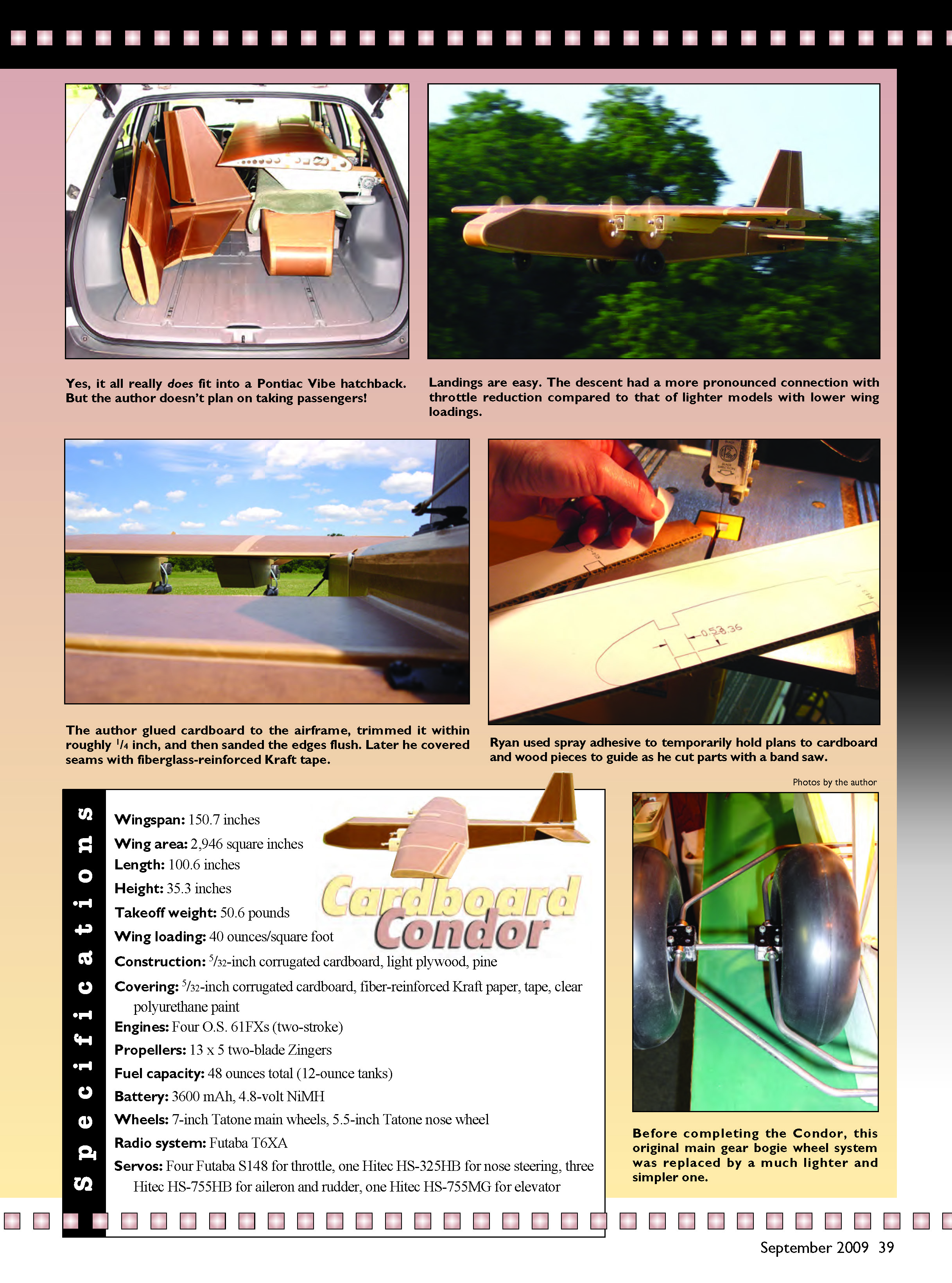
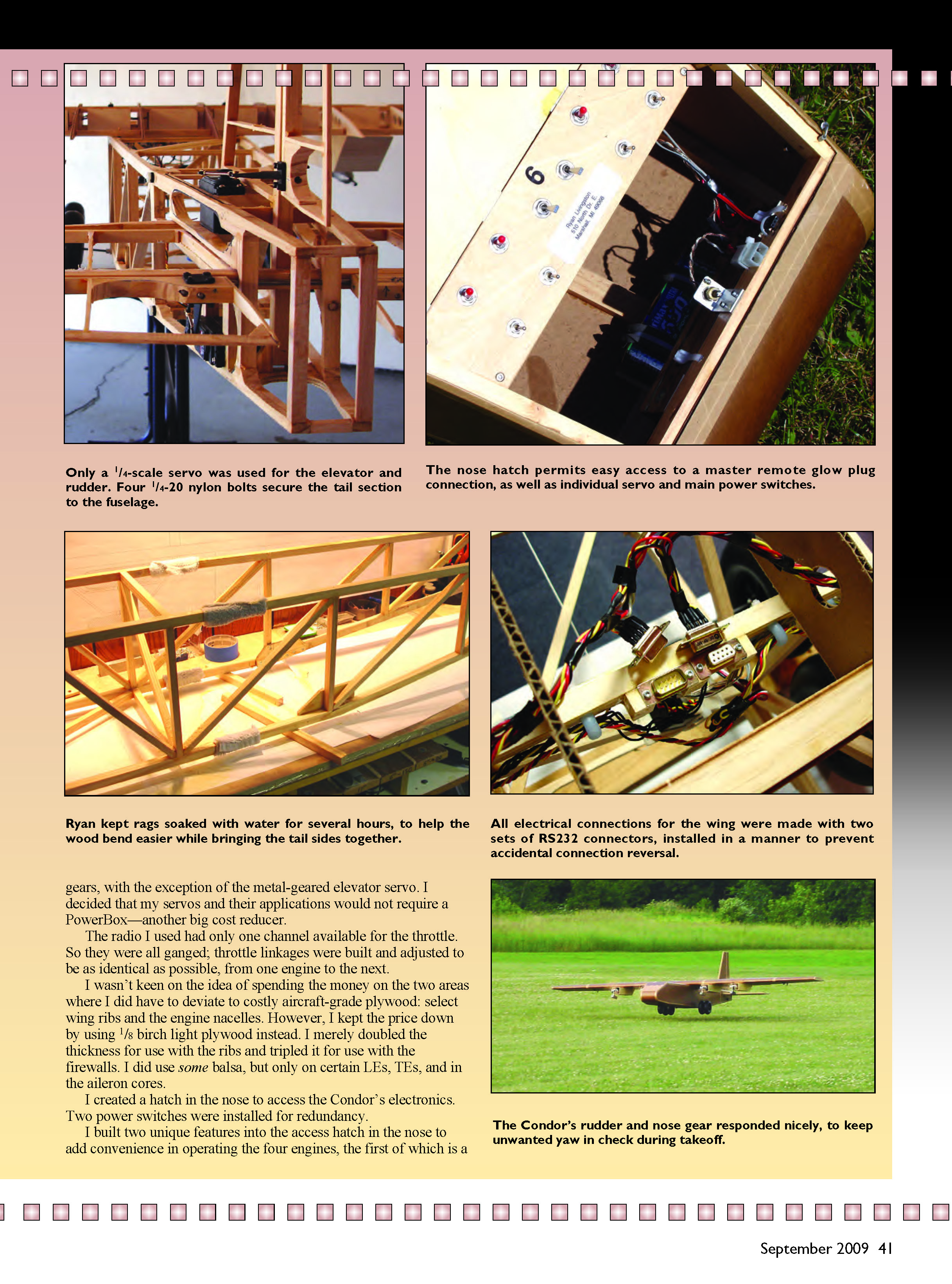
Another design requirement was that this 12.5-foot-wingspan airplane had to fit into my Pontiac Vibe. That’s where the removable empennage and wingtips came in. The 4-foot-span tail section is secured to the fuselage with four 1/4-20 nylon bolts. The servos are located in the tail; thus one only has to attach the servo connectors upon assembly. The center wing section supports all four engines, which helps keep assembly simple.
I wanted to spend as little money on this thing as possible. The Condor used one four-cell, 3600 mAh NiMH battery. A 1/4-scale analog servo was employed on each control surface, the elevator using only one. The throttle and nose-gear servos were standard size. All servos used nylon or Karbonite gears, with the exception of the metal-geared elevator servo. I decided that my servos and their applications would not require a PowerBox—another big cost reducer. The radio I used had only one channel available for the throttle, so the throttles were ganged; throttle linkages were built and adjusted to be as identical as possible from one engine to the next. I wasn’t keen on the idea of spending the money on additional throttle channels.
I wasn't keen on spending big money on aircraft-grade plywood for everything, so I used 1/8-inch birch light plywood where stronger plywood was needed. I doubled the thickness for ribs and tripled it for firewalls. I used some balsa in selected leading edges, trailing edges, and aileron cores.
I created a hatch in the nose to access the Condor's electronics. Two power switches were installed for redundancy. I built two unique features into the access hatch in the nose to add convenience in operating the four engines:
- A master remote glow-plug connection that supplies power to all four glow plugs through four toggle switches. It's wonderful; there's no fiddling with a glow starter near adjacent engines' spinning propellers. If you try this, make sure to use low-resistance wire and good connections. Glow plugs draw high current at low voltage and small amounts of resistance can compromise the circuit.
- Individual power switches for each throttle servo. This allows, for example, priming engine 4 with wide-open throttle while keeping the other three running engines at idle with their throttle servos powered down. This is handy during starting but creates a potential safety hazard because you lose instant ability to stop all engines with the transmitter while starting. I judged the trade-off acceptable based on field observations, though it's certainly a topic for debate.
All of the Condor's wheels had some form of spring suspension. The nose strut unit was kept simple and traveled through a couple of frame members. I originally installed brass sleeve inserts to receive the nose strut, but the strut tended to bind under side loads; holes in the wood frame used as guides worked better.
As I got closer to finishing and felt how 50 pounds carried, I made efforts to lighten things. The main gear went through a couple of revisions; the final undercarriage distributed weight better between the nose and main wheels by locating all four main wheels on one axle.
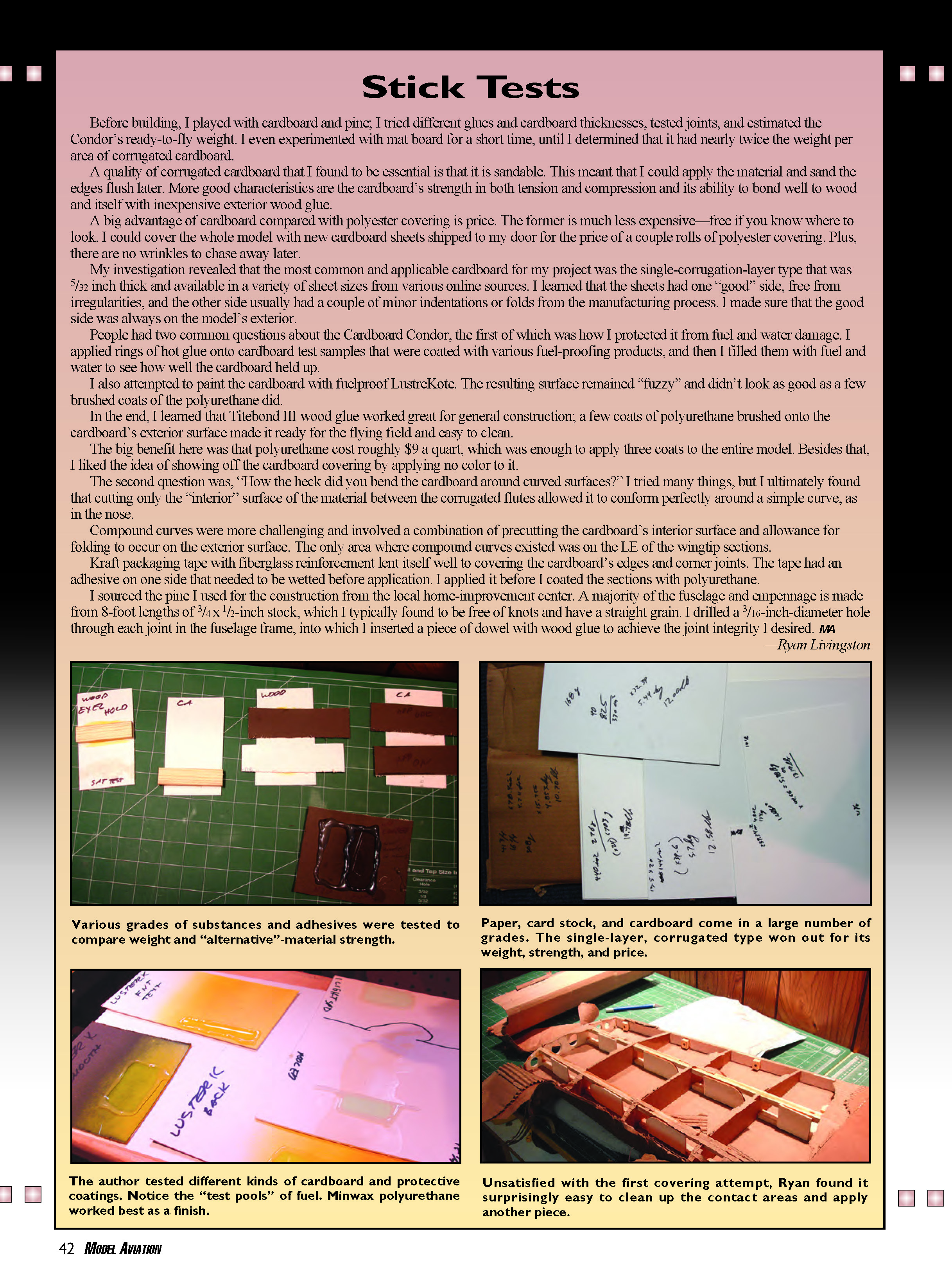
The engine nacelle-mounting and wing-mounting methods involved screw-and-nut fasteners through holes drilled into the wing. The wing uses a twin-main-spar design, which offers the nacelles good support. The wing didn’t have much fuselage weight to lift; bending stresses were spread somewhat evenly along the spars. Only four hardened-steel 8-32 screws were needed to lock the wing onto the fuselage frame.
Specifications
- Wingspan: 150.7 inches
- Wing area: 2,946 square inches
- Length: 100.6 inches
- Height: 35.3 inches
- Takeoff weight: 50.6 pounds
- Wing loading: 40 ounces/square foot
- Construction: 5/32-inch corrugated cardboard, light plywood, pine
- Covering: 5/32-inch corrugated cardboard, fiber-reinforced Kraft paper, tape, clear polyurethane paint
- Engines: Four O.S. 61FX (two-stroke)
- Propellers: 13 x 5 two-blade Zingers
- Fuel capacity: 48 ounces total (12-ounce tanks)
- Battery: 3600 mAh, 4.8-volt NiMH
- Wheels: 7-inch Tatone main wheels, 5.5-inch Tatone nose wheel
- Radio system: Futaba T6XA
- Servos:
- Four Futaba S148 for throttle
- One Hitec HS-325HB for nose steering
- Three Hitec HS-755HB for aileron and rudder
- One Hitec HS-755MG for elevator
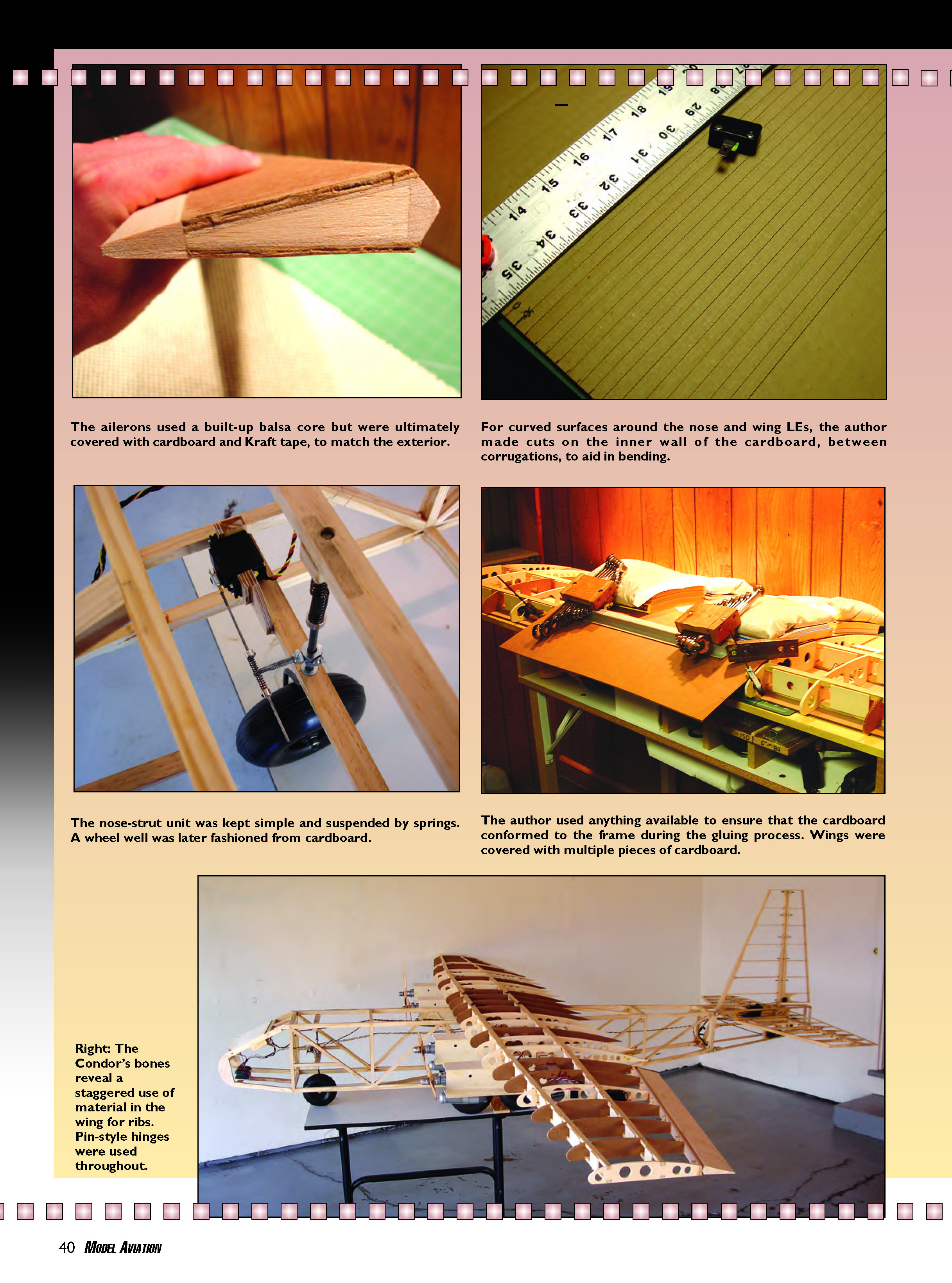
The ailerons used a built-up balsa core but were ultimately covered with cardboard and Kraft tape to match the exterior.
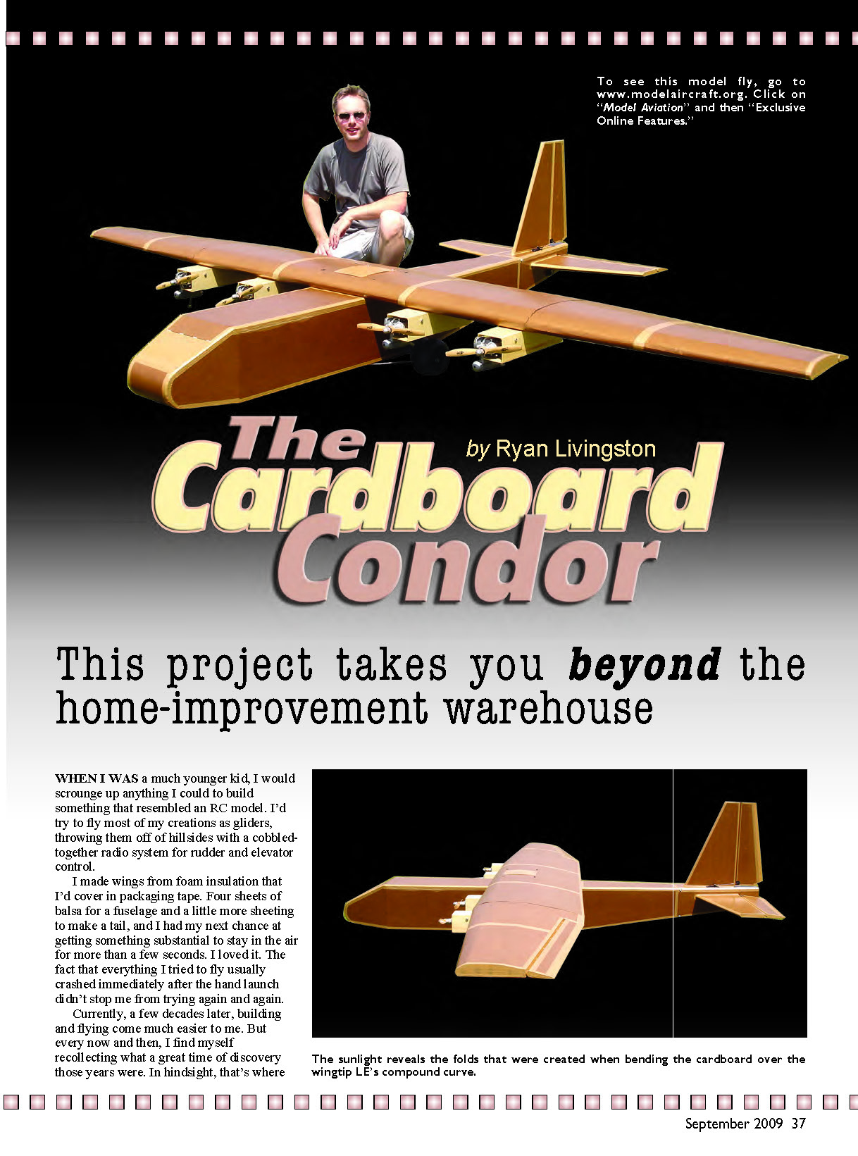
For curved surfaces around the nose and wing leading edges, I made cuts on the inner wall of the cardboard, between corrugations, to aid bending. For compound curves (limited to the leading edge of the wingtip sections), I combined interior precuts with allowance for folding on the exterior surface.
The nose-strut unit was kept simple and suspended by springs. A wheel well was later fashioned from cardboard. I used whatever was available to ensure the cardboard conformed to the frame during gluing. Wings were covered with multiple pieces of cardboard.
Right: the Condor's bones reveal a staggered use of material in the wing for ribs. Pin-style hinges were used throughout.
Stick Tests
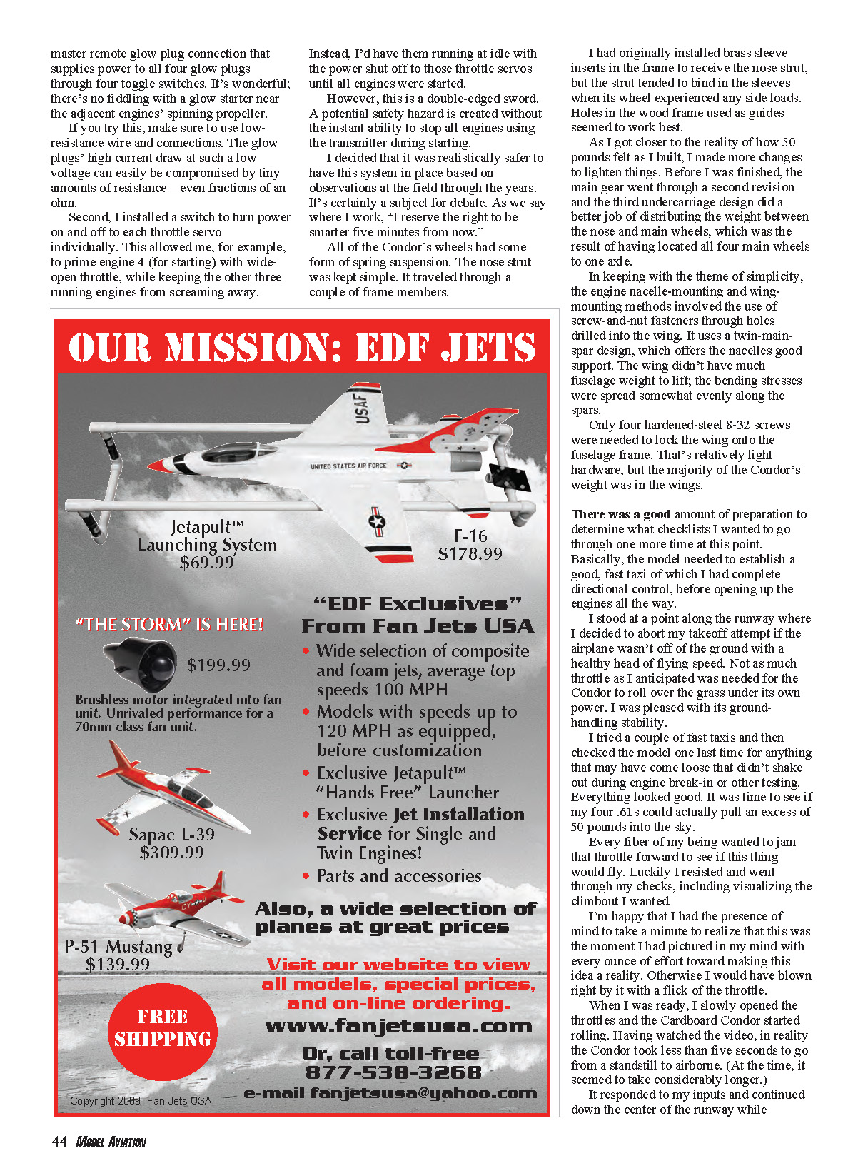
Before building, I played with cardboard and pine; I tried different glues and cardboard thicknesses, tested joints, and estimated the Condor's ready-to-fly weight. I even experimented with mat board for a short time, until I determined it had nearly twice the weight per area of corrugated cardboard.
A quality of corrugated cardboard that I found essential is that it is sandable. This meant I could apply the material and sand the edges flush later. More good characteristics are cardboard's strength in both tension and compression and its ability to bond well to wood and itself with inexpensive exterior wood glue.
A big advantage of cardboard compared with polyester covering is price. Cardboard is much less expensive—free if you know where to look. I could cover the whole model with new cardboard sheets shipped to my door for the price of a couple rolls of polyester covering. Plus, there are no wrinkles to chase away later.
The most common and applicable cardboard for my project was the single-corrugation-layer type that was 5/32-inch thick and available in various sheet sizes from online sources. I learned the sheets had one "good" side free from irregularities and the other side usually had minor indentations or folds from manufacturing. I made sure the good side was always on the model's exterior.
People had two common questions about the Cardboard Condor. First, how did I protect it from fuel and water damage? I applied rings of hot glue onto cardboard test samples that were coated with various fuel-proofing products, then filled them with fuel and water to see how well the cardboard held up. I also attempted to paint the cardboard with fuelproof LustreKote, but the resulting surface remained "fuzzy" and didn't look as good as a few brushed coats of polyurethane.
In the end I learned that Titebond III wood glue worked great for general construction; a few coats of brushed-on polyurethane to the cardboard exterior made it ready for the flying field and easy to clean. Polyurethane cost roughly $9 a quart and one quart was enough for three coats on the entire model. Besides that, I liked showing off the cardboard covering by applying no color to it.
The second question was, "How the heck did you bend the cardboard around curved surfaces?" I tried many things, but ultimately cutting only the interior surface between the corrugated flutes allowed it to conform perfectly around a simple curve, such as the nose. Compound curves required a combination of interior precuts and allowance for folding on the exterior surface.
Kraft packaging tape with fiberglass reinforcement worked well for covering cardboard edges and corner joints. The tape’s adhesive needed to be wetted before application. I applied it before coating the sections with polyurethane.
I sourced the pine from a local home-improvement center. Much of the fuselage and empennage is made from 8-foot lengths of 3/4 x 1/2-inch stock, typically free of knots and straight-grained. I drilled a 3/16-inch hole through each joint in the fuselage frame and inserted a dowel with wood glue to achieve joint integrity.
—Ryan Livingston
The Cardboard Condor - 2009/09 (Flight Report)
There was a good amount of preparation to determine which checklists I wanted to run through before the first flight. Basically, the model needed to establish a good, fast taxi with complete directional control before opening up the engines all the way.
I stood at a point along the runway where I decided to abort the takeoff if the airplane wasn't off the ground with a healthy head of flying speed. Not as much throttle as I anticipated was needed for the Condor to roll over grass under its own power. I was pleased with its ground-handling stability.
I tried a couple of fast taxis and then checked the model one last time for anything that may have come loose during engine break-in or other testing. Everything looked good. It was time to see if my four .61s could pull an excess of 50 pounds into the sky.
Every fiber of my being wanted to jam the throttle forward. Luckily I resisted and went through my checks, including visualizing the climbout I wanted. When I was ready, I slowly opened the throttles and the Cardboard Condor started rolling. Having watched the video, the Condor took less than five seconds to go from a standstill to airborne. It responded to my inputs and continued down the center of the runway while advancing to full throttle. The aircraft heaved itself off the ground and, with little complaint, answered my respectful request for a shallow climbout.
I kept the Condor on a nice climbing turn back over the field. Flying-wise, it looked fairly strong. I throttled the engines back and my nerves followed. After minor trimming, I knew I had a good airplane. The elevator was sensitive and I had to correct steeper banks with some opposite aileron, but I was in business. Wondering if and how a giant cardboard airplane would fly was over. It was "corrugated overcast."
After flying around and quickly gaining a feel for the model, I did one slow pass over the runway and saw that I could expect a fair amount of flying stability on the landing approach. The Condor settled downward so nicely that I thought, "What the heck; let's try a landing now." The weight and wing loading kept things moving slow enough for me to enjoy it. The model flew directly down to the runway, set its 7-inch wheels on the grass, and lumbered to a stop with four running engines. To say I felt good at that point is an understatement.
Since then I have run out a tank or two of fuel on a couple of occasions while flying. However, the relatively low wing loading for such a large airplane helped me get to an approach and landing each time. Each time an engine stopped I was in a position to immediately bring the running engines back to idle, so I haven't been put to a full engine-out test yet.
On landing, the long wingspan doesn’t threaten to drag a wingtip even with a healthy correctional bank while touching down. Landings with or without power seem easy. The relatively large vertical surface might give the Condor additional relief from uneven engine speeds.
I made small adjustments on a couple of throttle linkages to fine-tune engine synchronization. I noticed no adverse yaw in the air from uneven engine thrust. I could hear a couple of engines running slightly slower than others in their midrange and wanted to improve synchronization as a matter of good practice.
With a strong wing spar and joiner system, I was comfortable pulling a couple of Gs. On the second flight I performed two consecutive inside loops, starting from the bottom. Coming down on the backside the first time was a little scary, but the aircraft's rather blunt frontal profile seemed to keep the speed under control. The Condor doesn't resist inverted flight too much, either.
Could one engine taxi the Condor over grass? If not, could two? One inboard engine at full throttle would not move the Condor, even with a push. But both inboard engines would taxi it at half throttle. The four engines get a workout during flight, requiring much more throttle than I normally use to fly a single-engine, 60-size model. I like the concept that one engine is unable to taxi a four-engine model on grass, but two should be capable. It seems like a good check on engine selection, although there are many other factors.
Building a giant model mainly from cardboard and pine is possible. Only time will tell how it holds up with age. The Condor hasn’t experienced extreme highs in humidity and heat; I haven’t noticed issues with the cardboard’s stability in temperatures in the mid-80s with medium-high humidity.
I don’t recommend that everyone tries something similar. The Condor requires an increased level of attention to safety because of its experimental nature and relatively large size. The care it takes in handling and flying to avoid overloading the structure calls for a fair amount of experience.
I hope this project encourages you to consider new directions in your RC flying. After all, exploring and experimenting is what made flying possible in the first place.
Ryan Livingston [email protected]
Transcribed from original scans by AI. Minor OCR errors may remain.

