
Carl Goldberg Super Chipmunk EP ARF-2012/11
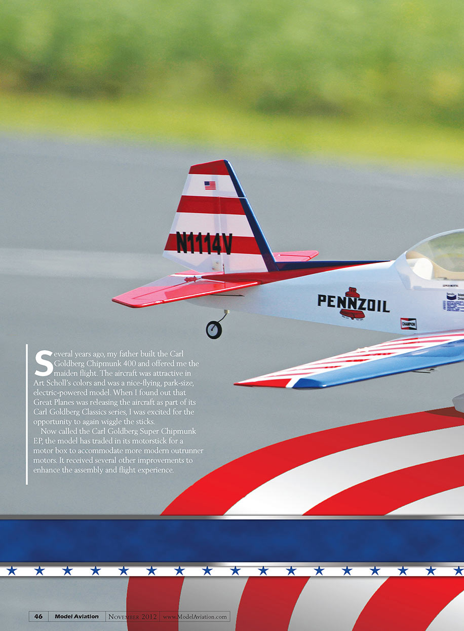
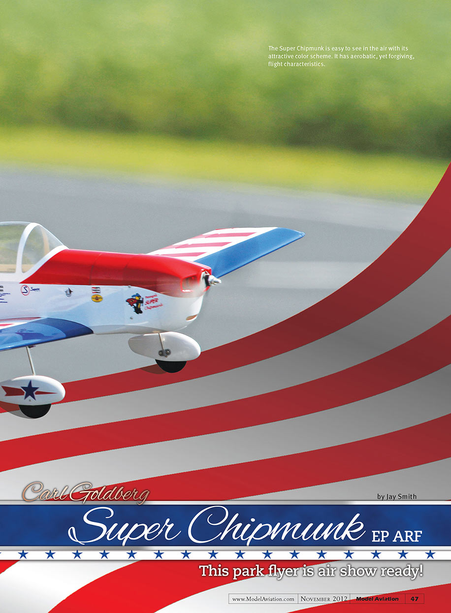
The Super Chipmunk is easy to see in the air with its attractive color scheme. It has aerobatic, yet forgiving, flight characteristics.
by Jay Smith [email protected]
Construction
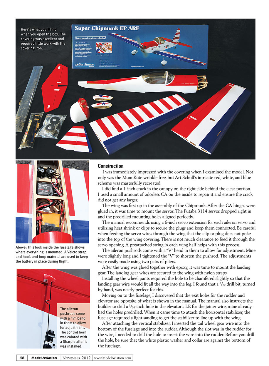
I was immediately impressed with the covering when I examined the model. Not only was the MonoKote wrinkle free, but Art Scholl’s intricate red, white, and blue scheme was masterfully recreated.
I did find a 1-inch crack in the canopy on the right side behind the clear portion. I used a small amount of odorless CA on the inside to repair it and ensure the crack did not get any larger.
The wing was first up in the assembly of the Chipmunk. After the CA hinges were glued in, it was time to mount the servos. The Futaba 3114 servos dropped right in and the predrilled mounting holes aligned perfectly. The manual recommends using a 6-inch servo extension for each aileron servo and utilizing heat shrink or clips to secure the plugs and keep them connected. Be careful when feeding the servo wires through the wing that the clip or plug does not poke into the top of the wing covering; there is not much clearance to feed it through the servo opening. A preattached string in each wing half helps with this process.
The aileron pushrods come with a "V" bend in them to allow for adjustment. Mine were slightly long and I tightened the "V" to shorten the pushrod. The adjustments were easily made using two pairs of pliers.
After the wing was glued together with epoxy, it was time to mount the landing gear. The landing gear wires are secured to the wing with nylon straps. Installing the wheel pants required the hole to be chamfered slightly so that the landing gear wire would fit all the way into the leg. I found that a 3/32-inch drill bit, turned by hand, was nearly perfect for this.
Moving on to the fuselage, I discovered that the exit holes for the rudder and elevator are opposite of what is shown in the manual. The manual also instructs the builder to drill a 1/16-inch hole in the elevator’s leading edge for the joiner wire; mine already had the holes predrilled. When it came time to attach the horizontal stabilizer, the fuselage required a light sanding to get the stabilizer to line up with the wing.
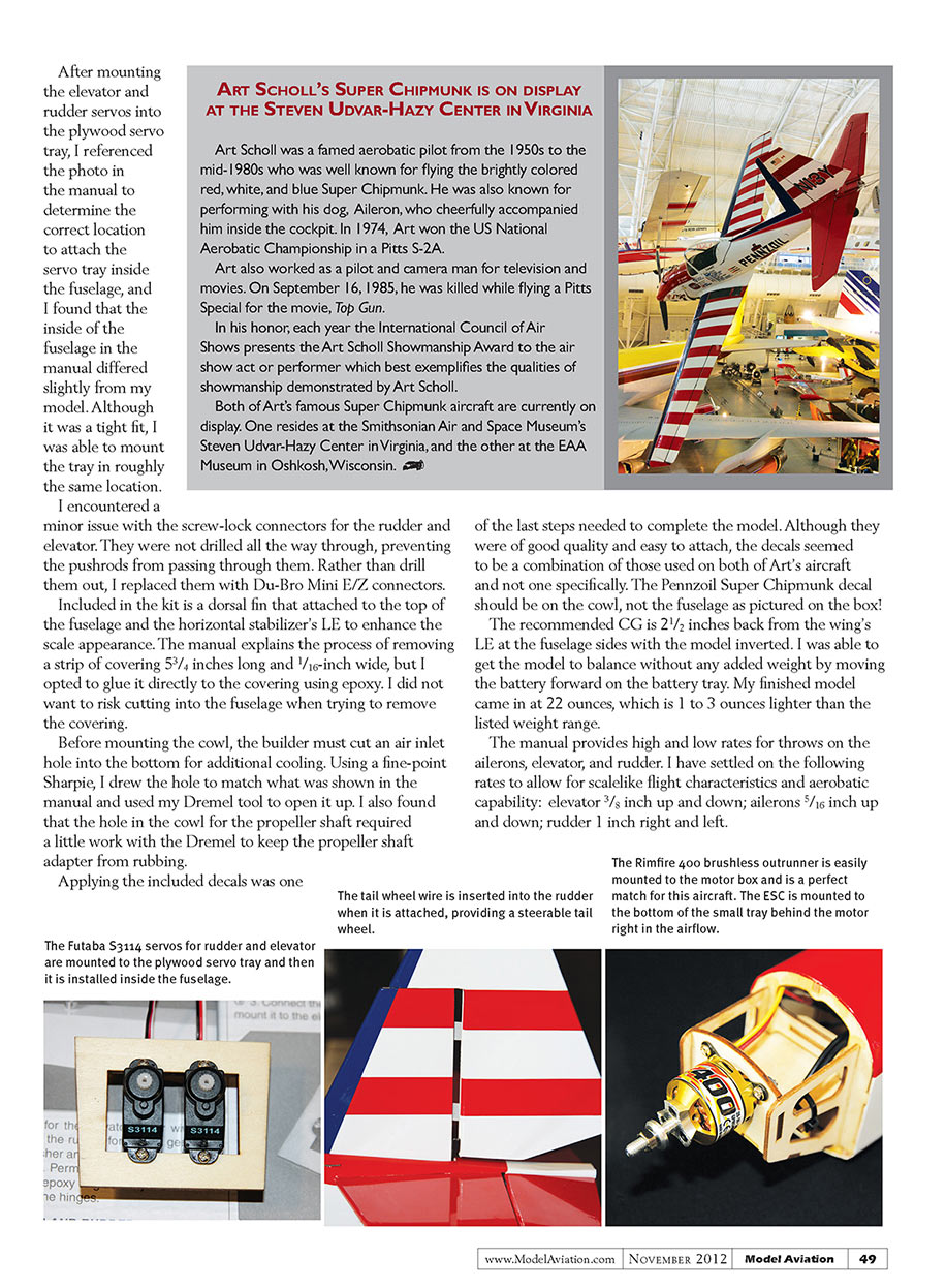
After attaching the vertical stabilizer, I inserted the tail-wheel gear wire into the bottom of the fuselage and into the rudder. Although the slot was in the rudder for the wire, I needed to drill the hole to insert the wire into the rudder. Before you drill the hole, be sure that the white plastic washer and collar are against the bottom of the fuselage.
After mounting the elevator and rudder servos into the plywood servo tray, I referenced the photo in the manual to determine the correct location to attach the servo tray inside the fuselage, and I found that the inside of the fuselage in the manual differed slightly from my model. Although it was a tight fit, I was able to mount the tray in roughly the same location.
I encountered a minor issue with the screw-lock connectors for the rudder and elevator. They were not drilled all the way through, preventing the pushrods from passing through them. Rather than drill them out, I replaced them with Du-Bro Mini E/Z connectors.
Included in the kit is a dorsal fin that attaches to the top of the fuselage and the horizontal stabilizer's leading edge to enhance the scale appearance. The manual explains the process of removing a strip of covering 5-3/4 inches long and 1/16-inch wide, but I opted to glue it directly to the covering using epoxy. I did not want to risk cutting into the fuselage when trying to remove the covering.
Before mounting the cowl, the builder must cut an air inlet hole into the bottom for additional cooling. Using a fine-point Sharpie, I drew the hole to match what was shown in the manual and used my Dremel tool to open it up. I also found that the hole in the cowl for the propeller shaft required a little work with the Dremel to keep the propeller shaft adapter from rubbing.
Applying the included decals was one of the last steps needed to complete the model. Although they were of good quality and easy to attach, the decals seemed to be a combination of those used on both of Art Scholl's aircraft rather than one specific scheme. The Pennzoil Super Chipmunk decal should be on the cowl, not the fuselage as pictured on the box!
The recommended CG is 2-1/2 inches back from the wing's leading edge at the fuselage sides with the model inverted. I was able to get the model to balance without any added weight by moving the battery forward on the battery tray. My finished model came in at 22 ounces, which is 1 to 3 ounces lighter than the listed weight range.
The manual provides high and low rates for throws on the ailerons, elevator, and rudder. I have settled on the following rates to allow for scale-like flight characteristics and aerobatic capability:
- Elevator: 3/8 inch up and down
- Ailerons: 5/16 inch up and down
- Rudder: 1 inch right and left
Flying
Because I had flown the earlier version of the Chipmunk, I knew I was in for a treat and sure enough, the new-and-improved Super Chipmunk did not disappoint. The model requires only slight rudder input to keep it tracking straight down the paved runway and is capable of becoming airborne at roughly half throttle.
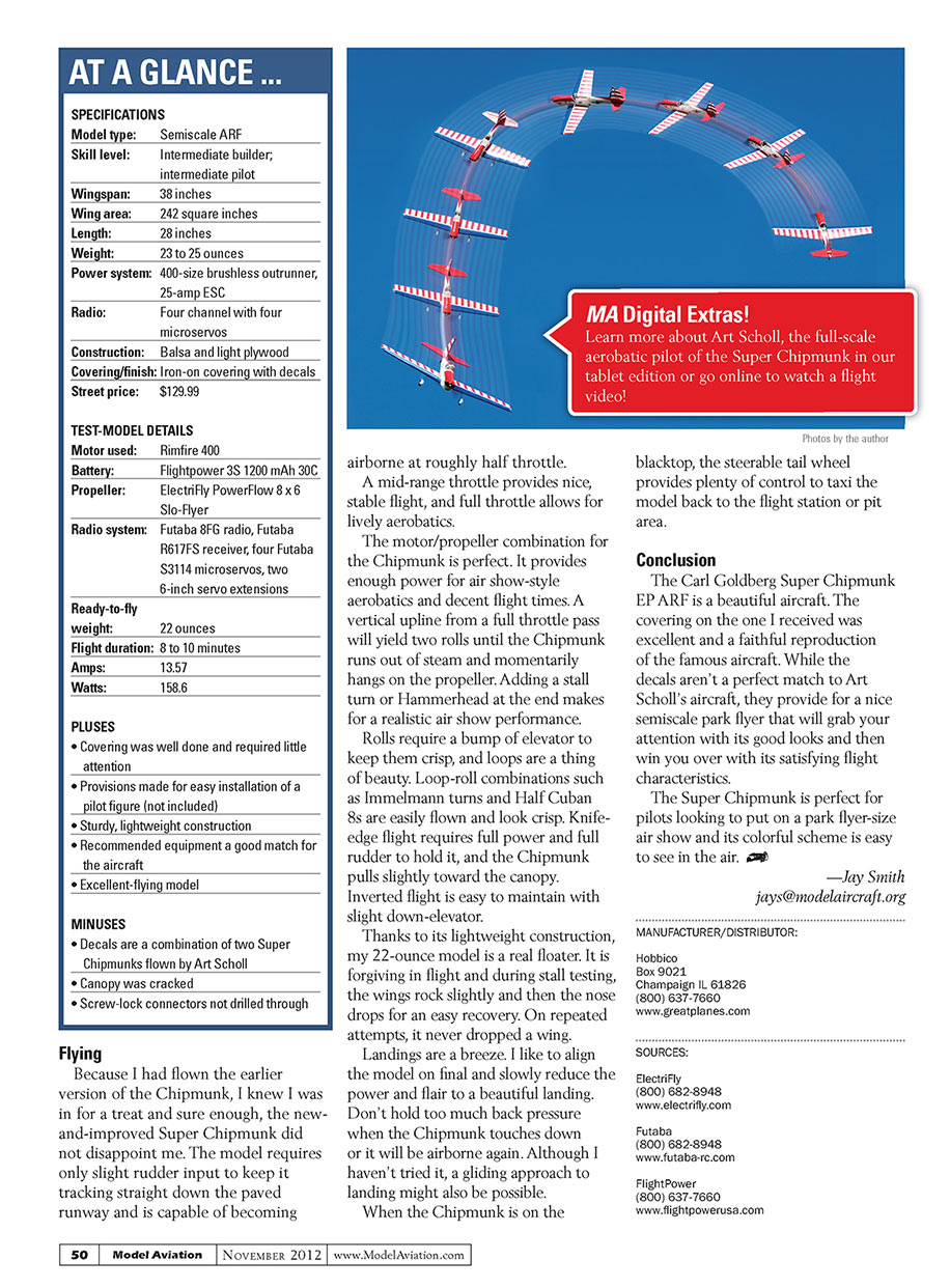
A mid-range throttle provides nice, stable flight, and full throttle allows for lively aerobatics. The motor/propeller combination for the Chipmunk is perfect. It provides enough power for air show–style aerobatics and decent flight times. A vertical upline from a full-throttle pass will yield two rolls until the Chipmunk runs out of steam and momentarily hangs on the propeller. Adding a stall turn or Hammerhead at the end makes for a realistic air show performance.
Rolls require a bump of elevator to keep them crisp, and loops are a thing of beauty. Loop-roll combinations such as Immelmann turns and Half Cuban 8s are easily flown and look crisp. Knife-edge flight requires full power and full rudder to hold it, and the Chipmunk pulls slightly toward the canopy. Inverted flight is easy to maintain with slight down-elevator.
Thanks to its lightweight construction, my 22-ounce model is a real floater. It is forgiving in flight and during stall testing, the wings rock slightly and then the nose drops for an easy recovery. On repeated attempts, it never dropped a wing.
Landings are a breeze. I like to align the model on final, slowly reduce the power, and flare to a beautiful landing. Don’t hold too much back pressure when the Chipmunk touches down or it will be airborne again. Although I haven’t tried it, a gliding approach to landing might also be possible.
When the Chipmunk is on the blacktop, the steerable tail wheel provides plenty of control to taxi the model back to the flight station or pit area.
Conclusion
The Carl Goldberg Super Chipmunk EP ARF is a beautiful aircraft. The covering on the one I received was excellent and a faithful reproduction of the famous aircraft. While the decals aren’t a perfect match to Art Scholl’s aircraft, they provide for a nice semiscale park flyer that will grab your attention with its good looks and then win you over with its satisfying flight characteristics.
The Super Chipmunk is perfect for pilots looking to put on a park-flyer–size air show and its colorful scheme is easy to see in the air.
—Jay Smith
Manufacturer / Distributor
- Hobbico
Box 9021 Champaign, IL 61826 (800) 637-7660 www.greatplanes.com
Sources
- ElectriFly
(800) 682-8948 www.electrifly.com
- Futaba
(800) 682-8948 www.futaba-rc.com
- FlightPower
(800) 637-7660 www.flightpowerusa.com
Transcribed from original scans by AI. Minor OCR errors may remain.

