
Carve Your Own Prop
John Van't-Haaff
Editor's note
This is not a beginner's project. Please study the text thoroughly, and be certain you fully understand the techniques involved before attempting to carve props.
MAKING YOUR OWN PROPELLERS can be challenging, rewarding, and fun. It can be handy, particularly for large, difficult-to-get props or for those with unusual pitches. It's also nice to be able to make your own laminated antique scale propeller, and it's handy to be able to make a prop you just ran out of—one that doesn't happen to be on the hobby shop shelf when you need it.
For the most part, the same principles apply to model props and full-size propellers. The theories, terms, and math can be pretty heavy reading. If there appears to be some oversimplification here, it's because I want to encourage those who would otherwise give up before they start, thereby missing out on a gratifying, often-overlooked part of the hobby.
Making propellers may not be for everyone, but if you can hang in there long enough to try, you will find it intriguing and addictive.
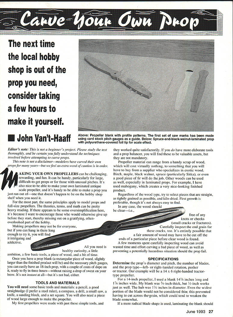
All you need is healthy curiosity, a little ambition, a few basic tools, a piece of wood, and a bit of time. Once you have a prop blank (a rectangular piece of wood, slightly larger than the finished product) and the necessary pitch gauges, you can easily have an 18-inch prop with a couple of coats of dope on it ready to fly in about three hours. It's not instant at all—but it's not bad, either.
Tools and Materials
You will need some basic tools and materials:
- Pencil
- Good straightedge (steel ruler recommended)
- Compass
- Drill
- Small saw (band saw, scroll saw, or hand saw)
- Knife
- Sanding block
- Set square
- Prop balancer (valuable but not mandatory)
- Piece of wood large enough to make the propeller
Propeller material can range from a handy scrap of wood (costing virtually nothing) to exotic woods from a supplier. Suitable woods include:
- Birch
- Maple
- Black walnut
- Spruce (particularly Sitka)
- Fir
- Mahogany (good for laminated, attractive finish)
Wood selection tips:
- Choose straight, tightly grained, kiln-dried wood.
- First growth is preferable.
- Wood should be clear—free of knots or checks (small cracks or fractures).
- Inspect end grain carefully; you may need to cut off ends to find clear wood.
- A few moments inspecting wood can avoid wasted effort and prevent a hazardous situation should the prop fail.
Specifications
Decide on the prop's diameter and pitch, the number of blades, and the prop type—left- or right-handed rotation, pusher or tractor. Our example here is a 14 x 6 right-handed tractor-type propeller.
Example blank dimensions for a 14-inch prop:
- Blank length: 14 1/8 inches
- Blank width: 1 7/8 inches
- Blank thickness: 5/8 inch (1/2 inch also works)
- Hub diameter: 1 1/4 inches
Notes on blade construction:
- Keep the widest portion of the blade not too thin to avoid cutting across the grain.
- Consider laminating for radical blade shapes or scimitar profiles to add strength.
- Number of blades affects blank construction:
- Two-bladed props and single-bladed counterbalanced props can often be solid.
- Three-bladed props generally should be laminated (unless bolted blades or machined hub).
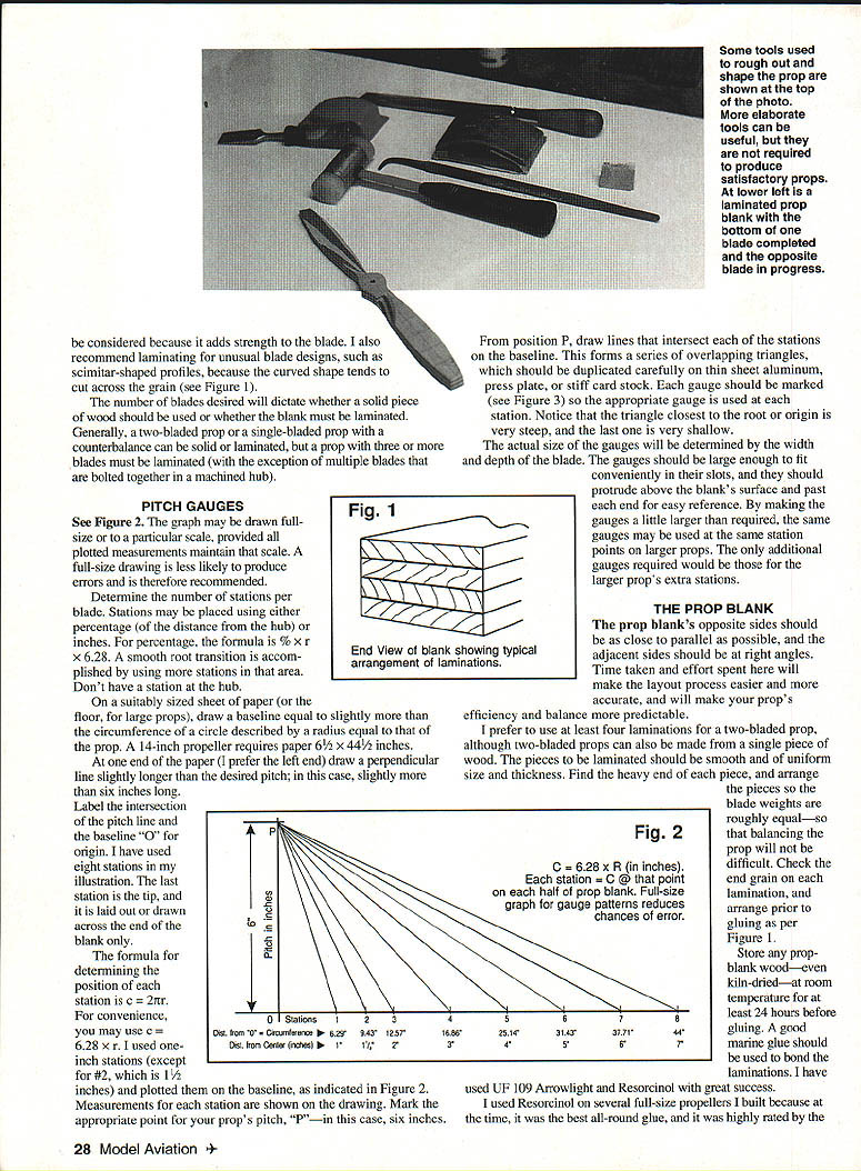
Pitch Gauges
- Draw the pitch graph full-size if possible (reduces errors).
- Determine the number of stations per blade. Stations may be placed by percentage of radius or by inches. Formula for circumference: c = 2πr (use c = 6.28 × r for convenience).
- For percentage spacing: use % × r × 6.28.
- Do not place a station at the hub. Use more stations near the root for a smooth transition.
Layout steps:
- On a suitably sized sheet of paper (or the floor for large props), draw a baseline slightly longer than the circumference described by the prop radius. Example: a 14-inch prop requires paper about 6-1/2 × 44-1/2 inches.
- At one end of the paper draw a perpendicular line slightly longer than the desired pitch (slightly more than 6 inches for a 6-inch pitch). Label the intersection of pitch line and baseline "0" for origin.
- Choose station spacing (example used eight stations; zero station is the tip and is drawn only across the end of the blank). Plot station positions on the baseline using the chosen spacing (example used one-inch stations except one at 1-1/2 inches).
- Mark the point for your prop's pitch "P" (6 inches in the example).
- From P, draw lines to intersect each station on the baseline—this makes overlapping triangles.
- Duplicate each triangle (gauge) on thin sheet aluminum, press plate, or stiff card stock. Mark each gauge so the correct one is used at each station.
Gauge sizing:
- Make gauges large enough to fit conveniently in slots and to protrude above the blank for easy reference.
- Slightly oversized gauges can be reused on larger props; only extra gauges are needed for additional stations.
The Prop Blank
- Opposite sides of the blank should be as parallel as possible and adjacent sides at right angles. Care here makes layout easier and improves accuracy, efficiency, and balance.
- Laminations:
- For two-bladed props, at least four laminations are preferred, though single-piece wood is possible.
- Laminations should be smooth, uniform in size and thickness.
- Find the heavy end of each lamination and arrange pieces so blade weights are roughly equal to ease balancing.
- Check grain direction and arrange laminations as needed (refer to Figure 1 in original).
- Store wood at room temperature for at least 24 hours before use, even kiln-dried wood.
- Recommended glue: good marine glues such as UF 109 Aerowright or Resorcinol (used successfully by the author). Avoid epoxy for laminations in this application; epoxy can delaminate after shock and is sensitive to surface prep and moisture.
- Gluing tips:
- Wipe wood surface with a damp rag before applying a light layer of glue.
- Brush glue evenly on each piece.
- Clamp the assembled blank securely for at least 24 hours (longer if possible).
- Clamp tightly and evenly to a straightedge (angle iron recommended) with as many clamps as practical.
- For small blanks, use a vise with soft jaws that cover the blank length; tighten clamps slowly and in sequence to maintain alignment and squareness.
- After drying:
- Remove squeeze-out glue with a knife, chisel, or screwdriver.
- Sand off excess glue before using a jointer.
- Use a jointer to true the blank if available.
- Make the blank a little larger and longer than the finished product to allow for machining and trimming.
Layout
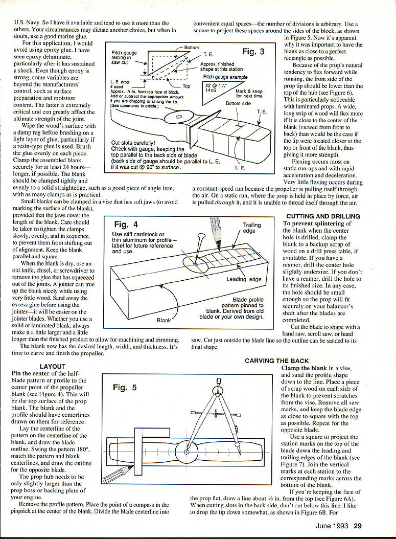
- Pin the center of the half-blade pattern to the center point of the propeller blank (this will be the top surface).
- Draw centerlines on both blank and profile for reference.
- Align the pattern centerline with the blank centerline and draw the blade outline.
- Swing the pattern 180°, match centerlines, and draw the outline for the opposite blade.
- The prop hub needs to be only slightly larger than the prop boss or backing plate of your engine.
Centerline and station transfer:
- Place the compass point in the center pinprick on the blank.
- Divide the blade centerline into convenient equal spaces (the number is arbitrary).
- Use a square to project these divisions around the sides of the block (see Figure 5). This is why a rectangular blank is important.
Tip placement and flex:
- Because props tend to flex forward when running, the front side of the prop tip should be lower than the top of the hub (particularly noticeable with laminated props).
- A wide, long strip of wood will flex more if the tip sits nearer the center (front-to-back) of the blank. Positioning the tip closer to the top or front of the blank increases strength.
- Flexing occurs most on static run-ups and rapid acceleration/deceleration; little flexing occurs at constant speed because the prop pulls itself through the air.
Cutting and Drilling
- To prevent splintering when drilling the center hole, clamp the blank to a backup scrap of wood on a drill press table if available.
- If you have a reamer, drill the center hole slightly undersize; otherwise drill to finished size. The hole should be small enough so the prop will fit securely on your balancer's shaft after blades are completed.
- Cut the blade shape with a band saw, scroll saw, or hand saw. Cut just outside the blade line so the outline can be sanded to final shape.
Carving the Back
- Clamp the blank in a vise and sand the profile down to the line. Place scrap wood on each side to prevent vise marks.
- Remove all saw marks and keep the blade edge as close to square with the top as possible. Repeat for the opposite blade.
- Use a square to project the station marks from the top down the leading and trailing edges of the blank (see Figure 7). Join the vertical marks at each station to the corresponding marks across the bottom of the blank.
If keeping the face flat:
- Draw a line about 1/8 inch from the top (Figure 6A). Do not cut below this line when making slots in the back.
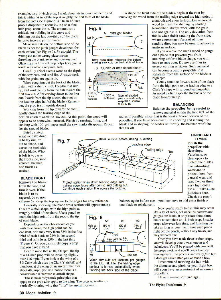
- The tip is usually dropped down somewhat. Example drops:
- 14-inch prop: about 3/16 inch at the tip, fairing within 1/8 inch of the top for roughly the first third from the root.
- 18-inch prop: about 5/16 inch drop at the tip.
- 9-inch prop: about 3/32 inch drop at the tip.
- The amount isn't critical, but building in this curve and thinning the last two-thirds of the blade helps performance.
Cutting and shaping the back:
- Make saw cuts on the bottom side of the blank per the pitch gauges for each station (see Figure 3). Be careful—wrong cuts can ruin the blank.
- Chisel excess wood to the depth of the saw cuts and sand flat. Always work with the grain.
- When roughing out the back, start with a sharp sickle (flat side up) and work gently from the hub toward the first saw cut. After carving down to the first cut, work from the tip toward the root on the leading-edge half.
- Working from tip toward root, gently chisel the trailing-edge portions down toward the saw cuts. The wood may appear terraced.
- Finish by rasping, filing, and sanding with 100-grit paper until saw marks disappear. Repeat for the second blade.
At this point the layout, drilling, cutting-to-shape, and back-side carving are complete. Next is carving the front side, sanding smooth, balancing, and finishing.
Blade Front
- Remove the blank from the vise and turn it over. If the blade is to be tapered, do so now. Keep the top square to the edges for reference.
- Blade cross-section typically approximates a Clark Y airfoil, with the high point at roughly one-third of the chord. Mark the high point from root to tip on each blade.
High point characteristics:
- The high point can be constant (about 33%), or vary:
- ~33% in the first third of the blade
- ~24% in the second third
- ~15% in the last third
- You can also copy a prop you have on hand.
Aerodynamic note:
- At 10,000 rpm a 14-inch prop tip travels slightly over 416 mph. Airfoil shapes differ significantly between low- and high-speed aircraft; the same principles apply to propellers—a vertically rotating wing that "lifts" the aircraft forward.
Shaping the front:
- Begin at the root and remove wood from the trailing edge toward the high point in a smooth, even fashion. Leave enough material for final sanding.
- Always work with the grain (except when finish sanding the front side, where a crosshatch oblique sanding pattern can be used to achieve a uniform surface).
- If you remove too much wood or gouge a piece preventing a uniform blade shape, start over. Do not use filler to correct carving mistakes—filler can separate at high rpm and become a deadly projectile.
- Gently sand the forward side from the high point to the leading edge into a Clark Y shape with a rounded leading edge. Taper blade thickness toward the tip.
Balancing
- Balance the propeller, removing material within the first 40% of the radius if possible, since that portion is the least efficient.
- If you selected and prepared the blank carefully and shaped both blades uniformly, the balance should be close.
- Recheck balance after finishing; you may need to add finish to one blade to rebalance.
Finish and Flying
- Finish options: clear dope, Varathane, or clear epoxy to protect the blades from moisture and wear.
- Apply two or three very light coats—be judicious.
- Check balance again before use; finishing can change balance.
- Once finished, you're ready to fly. It may seem like a lot of work, but once patterns and gauges are made, an 18-inch prop can be completed in about three hours. Smaller props take less time; finishing can take as long as you like.
- Some props have been used straight off the bench and worked fine.
- After making several props you'll develop shortcuts and techniques. The process gets easier and the results will please you.
Mark the hub with diameter and pitch, or your flight box will soon contain an assortment of unknown propellers.
Have fun—and soft landings!
The Flying Dutchman
Transcribed from original scans by AI. Minor OCR errors may remain.

