
CESSNA172
Presented as a realistic sport job, this 40-powered gem can serve as an intermediate trainer to help landings and use of throttle techniques, providing hours of easy stick time. —Fred Peese
Editor's note: Although the ever-popular Cessna has often been modeled, this exceptional project was too much to resist—especially because of the designer's reputation for skillfully crafted birds with superior handling characteristics.
TEN years ago I built a Cessna Skyhawk designed by Jess Kriser and it was with that airplane I learned to fly RC. I had previously built several machines that lasted a couple of flights or attempts at flight, but it was the Skyhawk, starting with an Enya 15 and rudder-only control, progressing to a KB 19 with rudder and elevator Galloping Ghost control, to finally a KB 35 and my first proportional radio using rudder, elevator and throttle controls that saw me through that difficult period. I flew the Skyhawk for at least two years, logging hundreds of flights, before I gave it away to another fledgling pilot. That man flew my Skyhawk for a year before he, in turn, passed it on. That original Skyhawk was rebuilt several times and has had at least two other owners that I know about and just last year I heard that it was still flying.
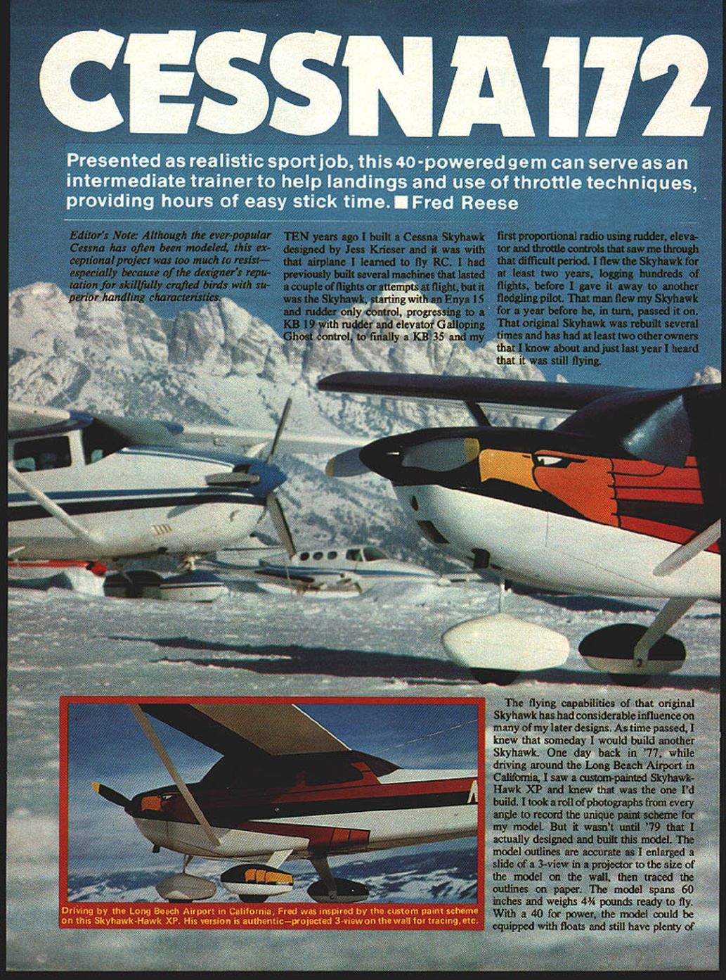
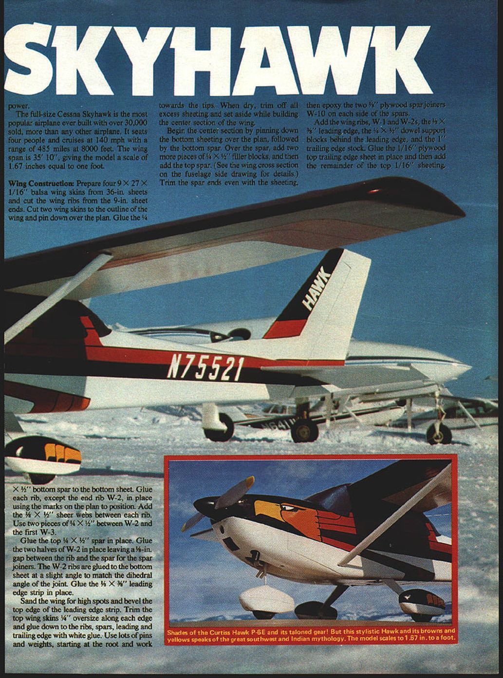
The flying capabilities of that original Skyhawk had considerable influence on many of my later designs. As time passed, I knew that someday I would build another Skyhawk. One day back in '77, while driving around the Long Beach Airport in California, I saw a custom-painted Skyhawk—Hawk XP—and knew that was the one I'd build. I took a roll of photographs from every angle to record the unique paint scheme for my model. But it wasn't until '79 that I actually designed and built this model. The model outlines are accurate as I enlarged a slide of a 3-view in a projector to the size of the model on the wall, then traced the outlines on paper.
The model spans 60 inches and weighs 4-1/2 pounds ready to fly. With a .40 for power, the model could be equipped with floats and still have plenty of power. The full-size Cessna Skyhawk is the most popular airplane ever built with over 30,000 sold, more than any other airplane. It seats four people and cruises at 140 mph with a range of 485 miles at 8,000 feet. The wing span is 35' 10", giving the model a scale of 1.67 inches = 1 foot.
Wing Construction
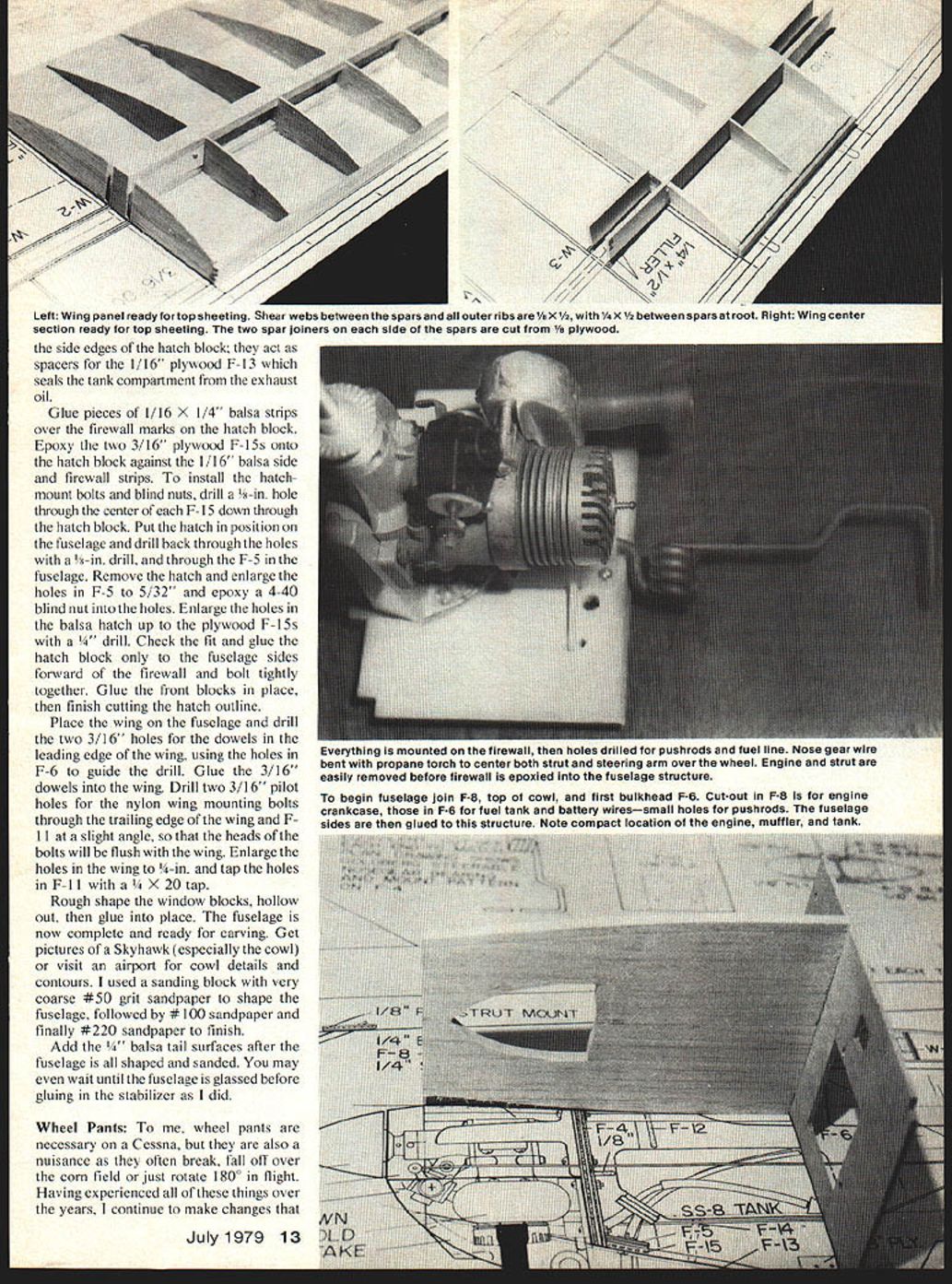
- Prepare four 9 x 27 x 1/16" balsa wing skins from 36-inch sheets and cut the wing ribs from the 9-inch sheet ends.
- Cut two wing skins to the outline of the wing and pin down over the plan. Glue the 1/4 x 1/2" bottom spar to the bottom sheet.
- Glue each rib (except the end rib W-2) in place using the marks on the plan to position. Add 1/8 x 1/4" shear webs between each rib. Use two pieces of 1/4 x 3/4" between W-2 and the first W-3.
- Glue the top 1/4 x 3/4" spar in place. Glue the two halves of W-2 in place leaving a 1/8" gap between the rib and the spar for the spar joiners. The W-2 ribs are glued to the bottom sheet at a slight angle to match the dihedral angle of the joint. Glue the 1/4 x 3/8" leading edge strip in place.
- Sand the wing for high spots and bevel the top edge of the leading edge strip. Trim the top wing skins 1/4" oversize along each edge and glue down to the ribs, spars, leading and trailing edge with white glue. Use lots of pins and weights, starting at the root and working toward the tips. When dry, trim off all excess sheeting and set aside while building the center section of the wing.
Center section:
- Pin down the bottom sheeting over the plan, followed by the bottom spar. Over the spar, add two more pieces of 1/4 x 3/4" filler blocks, and then add the top spar. (See the wing cross section on the fuselage side drawing for details.)
- Trim the spar ends even with the sheeting, then epoxy the two 3/8" plywood spar joiners W-10 on each side of the spars.
- Add wing ribs W-1 and W-2s, the 1/2 x 3/8" leading edge, the 1/4 x 1/2" dowel support blocks behind the leading edge, and the 1/8" trailing edge stock. Glue the 1/16" plywood top trailing edge sheet in place and then add the remainder of the top 1/16" sheeting. Allow to dry and trim all excess sheeting.
- Trial fit the wing panels to the center section and then epoxy the wing panels to the center section, blocking up each wing tip 2 inches. If building in ailerons, the dihedral can be reduced to 1 inch per tip. After the wing is joined, add the 1/4 x 3/8" leading edges and the wing tip blocks. Rough shape the blocks and leading edge (a razor saw and plane work well), then finish shaping with sandpaper. Some filler will be required on the center section behind the front window block.
Fuselage Construction
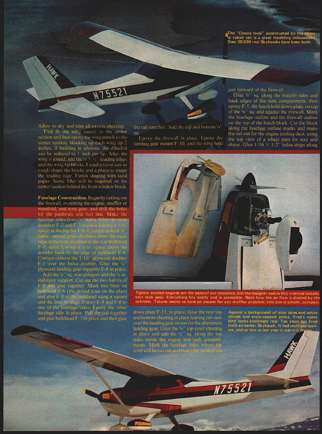
- Begin by cutting out the firewall, mounting the engine, muffler or manifold, and nose gear, and drill the holes for the pushrods and fuel line.
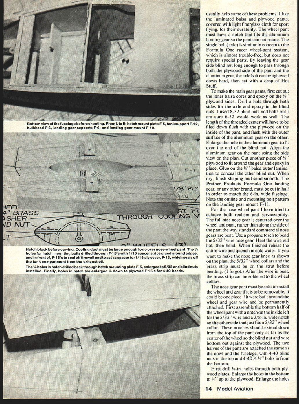
- Make the fuselage sides from 3/32" balsa. Glue the nose doublers F-2 and F-3 in place leaving 3/8" space at the top for F-8. Contact-cement 1/8" balsa vertical-grain doublers from the back edge of the nose doublers to the rear bulkhead F-7, again leaving 3/8" space above the doubler back to the edge of bulkhead F-6. Contact-cement the 1/16" plywood doubler F-1 over the balsa doubler. Glue the 1/8" plywood landing gear supports F-9 in place.
- Add the 1/4" sq. rear stringers and the 1/8" stabilizer support. Cut out the two halves of F-8 and glue together. Mark two lines on bulkhead F-6 (the dotted lines on the plan) and glue F-8 to the bulkhead using a square and the lines to align. Epoxy F-8 and F-6 to one of the fuselage sides. Epoxy the other fuselage side in place. Pull the tail together and glue bulkhead F-7 in place and then glue the tail together. Add the top and bottom 1/4" sq.
- Epoxy the firewall in place. Epoxy the landing gear mount F-10 and the wing hold-down plate F-11 in place. Glue the rear top and bottom sheeting in place leaving cutouts over the landing gear mount for the aluminum landing gear. Glue the 1/8" top cowl sheeting in place and add the 1/8" sq. along the top sides inside the engine and tank compartments. Mark the fuselage sides where the cowl will be cut out and make the vertical cut just forward of the firewall.
- Glue 3/8" sq. along the bottom sides and back edges of the tank compartment, then epoxy F-5, the hatch hold-down plate, on top of the 1/8" sq. and against the firewall. Mark the fuselage outline and the firewall outline on the top of the hatch block. Cut the block along the fuselage outline marks and make the cutout for the engine cooling duct, using the top view of a wheel pant for size and shape.
- Glue 1/16" x 1/4" balsa strips over the firewall marks on the hatch block. Epoxy two 3/16" plywood F-15s onto the hatch block against the 1/16" balsa side firewall strips. Install hatch-mount bolts and blind nuts. Drill a 3/8" hole through the center of F-15 down through the hatch block. Put the hatch in position on the fuselage and drill back through the holes (3/8") through F-5 and the fuselage. Remove the hatch and enlarge the holes in F-5 to 5/32". Epoxy 4-40 blind nuts in place. Enlarge the holes in the balsa hatch up into the plywood F-15s as required and check the fit. Glue the hatch block to the fuselage sides forward of the firewall, bolting tightly together. Glue front blocks in place and finish cutting the hatch outline.
- Place the wing on the fuselage. Drill two 3/16" holes for dowels in the leading edge of the wing using holes in F-6 as a guide; glue 3/16" dowels in the wing. Drill two 3/16" pilot holes for the nylon wing-mounting bolts through the trailing edge of the wing and F-11 at a slight angle so the heads of the bolts will be flush with the wing. Enlarge the holes in the wing to 7/64" and tap the holes in F-11 for 4-40 x 20.
- Rough shape the window blocks, hollow them out and glue in place. The fuselage is now complete and ready for carving. Get pictures of a Skyhawk, especially the cowl; visit an airport. Cowl details and contours were used to shape the cowl. Use a sanding block with very coarse #50 grit sandpaper to shape the fuselage, followed by #100 sandpaper and finally #220 for the finish. Add the four balsa tail surfaces after the fuselage is shaped and sanded; you may wait until the fuselage is glassed before gluing the stabilizer.
Notes:
- Everything should be mounted and firewall holes drilled, pushrods and fuel line installed before permanently joining key structures.
- The nose-gear wire can be bent with a propane torch; center both strut steering arms over the wheel. The engine strut can be removed before the firewall is epoxied.
Wheel Pants
Wheel pants are necessary for the Cessna look but are a nuisance and often break off. Having experienced problems over the years, I continue to make changes to improve durability and serviceability.
- Use laminated balsa/plywood pants covered with light fiberglass cloth for good durability in sport flying. The wheel pant must have a notch that fits the aluminum landing gear so the pant cannot rotate on the single axle bolt. A Formula-racer wheel-pant system is almost trouble-free but requires special parts: leave the gear-side blind nut long enough to pass through both plywood side pant and aluminum gear axle so the bolt can be tightened down hard and set.
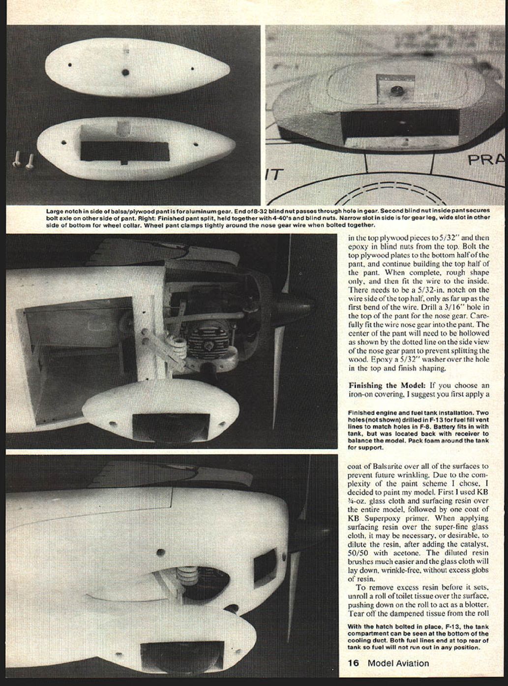
- Make the main gear pants by first cutting out the inner balsa cores and epoxying 1/8" plywood sides. Drill a hole through both sides for the axle; epoxy blind nuts are used. I used 8-32 blind nuts and bolts but 6-32 would work well. The length of the threaded center will have to be filed down flush with the plywood inside the pant so the outer surface of the pant is flush with the aluminum gear. Enlarge the hole in the aluminum gear to fit over the end of the blind nut. Align the aluminum gear and pant using the side-view plan. Cut another piece of wood to fit around the gear and epoxy in place. Glue an outer lamination to conceal the other blind nut. When dry, finish shaping and sand smooth.
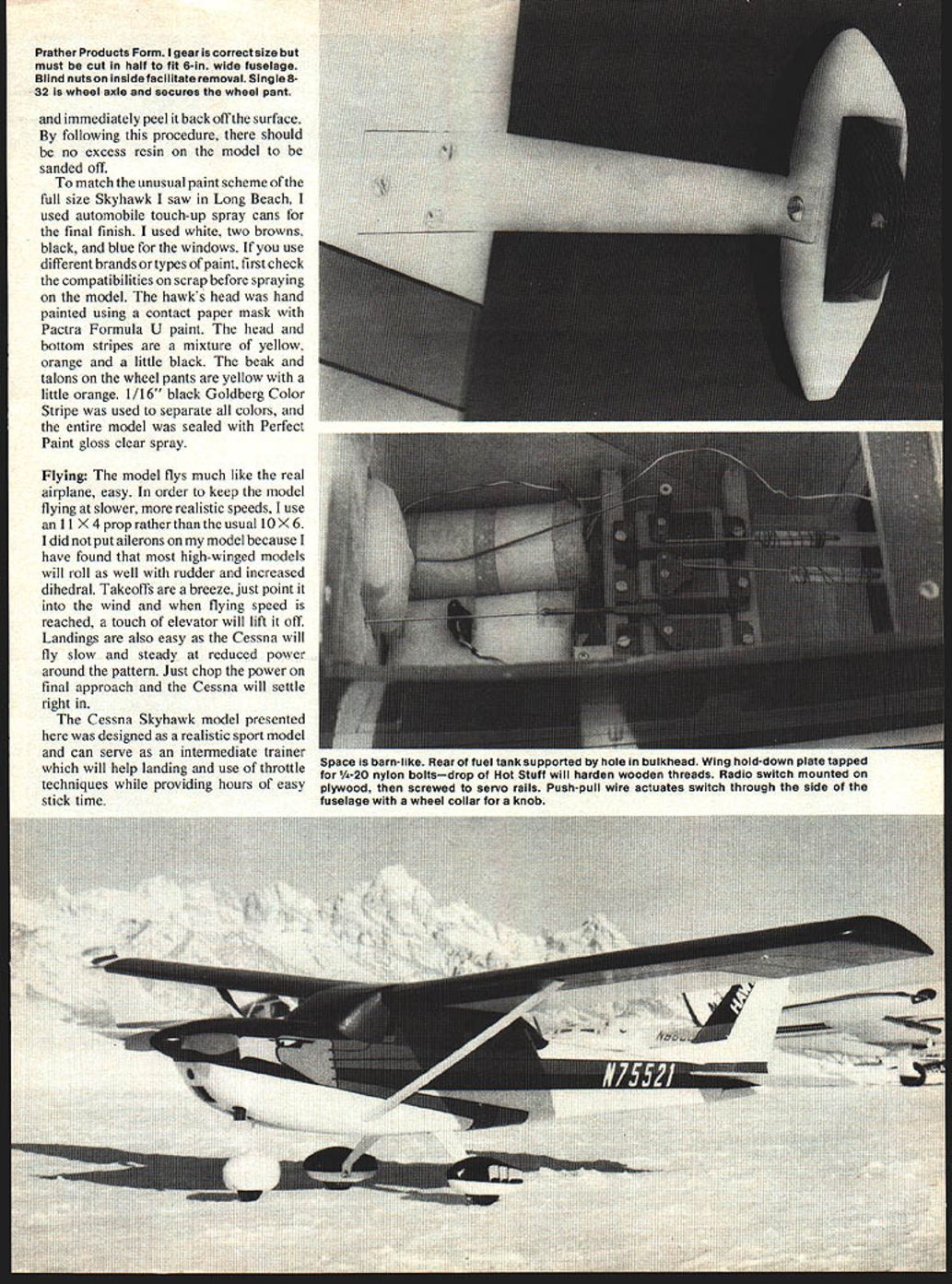
- Prather Products Formula landing gear and other brands must be cut in half to match a 6-inch wide fuselage. Note the outline and the mounting bolt pattern for the landing gear mount F-11 and the nose wheel pant.
Nose gear and pant:
- I prefer the full-size nose gear centered over the wheel pant rather than alongside the pant as on some commercial nose gears. Use a propane torch to bend 5/32" wire for the nose gear. Heat the wire red hot to bend; when finished, reheat the entire wire and quench in cold water if you want to form the nose-gear knee shown on the plan. Fit 5/32" wheel collars and a brass strip to the strut before bending. After bending, solder the brass strip and fit wheel collars.
- The nose wheel pant must be split to install the wheel gear if it is removable; otherwise the pant can be built around the wheel gear wire and attached permanently. First assemble the bottom half of the pant and notch the inside left for the 5/32" wire. Cut a 3/8" wide notch on the other side to fit the 5/32" wheel collar. These notches should extend down about 1/4" from the top of the pant—only as far as the center of the wheel—so the blind nut and wire bottom out against the plywood. Glue the bottom half to the top half, fit the 5/32" wire into the notches so the wheel collars are held tightly, epoxy the seam and the axle blind nut into the pant. When dry, finish shaping and sand smooth.
- First drill 1/8" holes through both plywood plates for the pant. Enlarge the holes in the bottom to 1/4" up to the plywood. Enlarge the holes in the top plywood pieces to 5/32" and then epoxy in blind nuts from the top. Bolt the top plywood plates to the bottom half of the pant, and continue building the top half of the pant. When complete, rough shape only, then fit the wire to the inside. There needs to be a 5/32" notch on the wire side of the top half only as far up as the first bend of the wire. Drill a 3/16" hole in the top of the pant for the nose gear. Carefully fit the wire nose gear into the pant. The center of the pant should be hollowed as shown by the dotted line on the side view of the nose gear pant to prevent splitting the wood. Epoxy a 5/32" washer over the hole in the top and finish shaping.
Finishing the Model
- If you choose an iron-on covering, first apply a coat of Balsarite over all surfaces to prevent future wrinkling.
- For painted finishes: I used KB 4-oz. glass cloth and surfacing resin over the entire model, followed by one coat of KB Superpoxy primer. When applying surfacing resin over super-fine glass cloth, it may be desirable to dilute the resin, after adding the catalyst, 50/50 with acetone. The diluted resin brushes much easier and the glass cloth will lay down, wrinkle-free, without excess globs of resin.
- To remove excess resin before it sets, unroll a roll of toilet tissue over the surface, pushing down on the roll to act as a blotter. Tear off the dampened tissue from the roll and immediately peel it back off the surface. By following this procedure, there should be no excess resin on the model to be sanded off.
- For the paint scheme I used automobile touch-up spray cans for the final finish: white, two browns, black, and blue for the windows. If you use different brands of paint, first check compatibility on scrap. The hawk's head was hand-painted using a contact-paper mask with Pactra Formula U paint. The head and bottom stripes are a mixture of yellow, orange and a little black. The beak and talons on the wheel pants are yellow with a little orange. 1/16" black Goldberg Color Stripe was used to separate all colors, and the entire model was sealed with Perfect Paint gloss clear spray.
Flying
- The model flies much like the real airplane—easy and predictable. To keep the model flying at slower, more realistic speeds, I use an 11 x 4 prop rather than the usual 10 x 6.
- I did not install ailerons on my model because most high-winged models will roll adequately with rudder and increased dihedral.
- Takeoffs: point into the wind and when flying speed is reached, a touch of elevator will lift it off.
- Landings: the Cessna will fly slow and steady at reduced power around the pattern. Just chop the power on final approach and the Cessna will settle right in.
The Cessna Skyhawk model presented here was designed as a realistic sport model and can serve as an intermediate trainer which will help landing technique and throttle control while providing hours of easy stick time.
CESSNA 172 SKYHAWK
DESIGNED AND DRAWN BY FRED PEESE
FULL-SIZE PLANS AVAILABLE: SEE PAGE 128
Transcribed from original scans by AI. Minor OCR errors may remain.

