
CG for Canards
John Hunton
Using the simple formula and experimental data provided here, your canard design doesn't have to fall victim to the effects of Reynolds number.
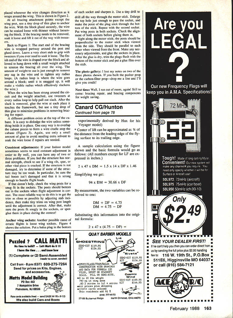
Luther Hux has designed a remarkable series of model aircraft, ranging from the Snapshot series to parafoils, space-planes, and now the Voyager. Designing a successful flying model of the Voyager was a very challenging endeavor. That Mr. Hux employed, in developing the Voyager, what in my opinion is one of the higher forms of design development — the "cut-and-try" model aviation method — is also to his credit. The truly amazing thing, though, is that Luther's design was accomplished first in a radio-controlled model, and then in a CL version.
With the recent outstanding success of the Voyager aircraft, many modelers will undoubtedly try to build and fly this configuration. Unfortunately, because of difficulties in locating the proper balance point and because of scale (Reynolds number) effects, there may be few successes. It is the purpose of this article to point out some methodologies that will help the modeler establish good beginning approximations, and, hopefully, point him toward a successful design.
Methods
- Build a scaled hand-launch glider model of your design. By test-flying this glider model and experimentally determining the best balance point, then scaling this information up and applying it to your powered model, you'll be able to achieve a good approximation.
- Proportionate loading of the flying surfaces (method used by Burt Rutan). For a canard design to be aerodynamically stable, the foreplane must carry more weight per unit area than the mainplane. Ratios used by Rutan have varied from 1.5:1 to 3:1, probably representing a useful range of center-of-gravity (CG) travel for piloted aircraft. Unfortunately, models cannot tolerate such a wide CG range. A sample calculation based upon Hux's successful model can serve as an example of how an optimum CG point can be selected, and as a procedure for other models.
- Use the classic formulas developed by Dr. Joseph Foa in "Proportioning a Canard Airplane for Longitudinal Stability and Safety Against Stall" (on file at the AMA Renaud Research Library in Reston). These formulas require information that is difficult for the modeler to obtain (low Reynolds number airfoil data); however, with approximations they show that the CG range for a full-sized canard is proportionately much larger than that for a model — illustrating the modeler's challenge.
Additional clues from Dr. Foa's work include using a more efficient airfoil for the foreplane than for the mainplane (a philosophy used by Rutan) and the requirement for a higher decalage angle in a canard (up to 5°).
Basic formula
The basic formula used is:
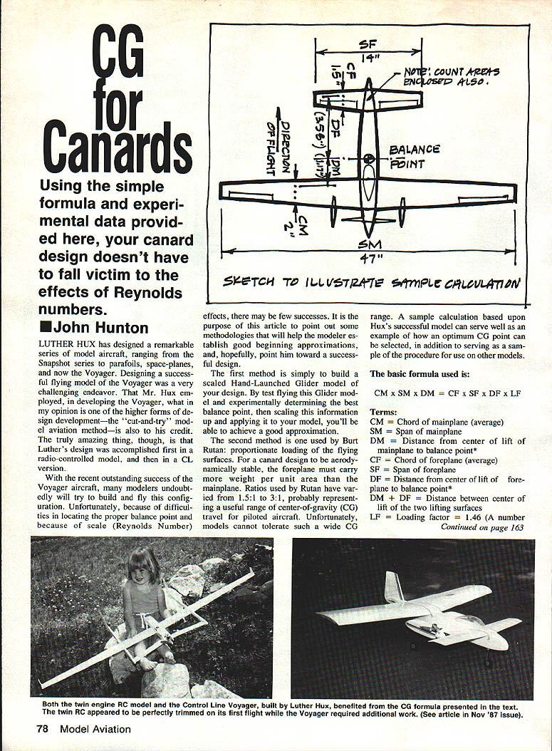
CM × SM × DM = CF × SF × DF × LF
Where:
- CM = Chord of mainplane (average)
- SM = Span of mainplane
- DM = Distance from center of lift of mainplane to balance point
- CF = Chord of foreplane (average)
- SF = Span of foreplane
- DF = Distance from center of lift of foreplane to balance point
- LF = Loading factor = 1.46 (a number experimentally derived by Hux for his Voyager model)
Notes:
- DM + DF = Distance between centers of lift of the two lifting surfaces.
- Center of lift can be approximated as 3/4 of the distance from the leading edge of the flying surface to its trailing edge.
Sample calculation
(All numbers except LF are in inches.)
Given (from the figure in the original example): 2 × 47 × DM = 1.5 × 14 × DF × 1.46
Simplify the right-hand side: 94 × DM = 30.66 × DF
By measurement: DM + DF = 4.75
So: DM = 4.75 − DF
Substitute into the formula: 2 × 47 × (4.75 − DF) = 30.66 × DF
Which gives: 94 × 4.75 − 94 DF = 30.66 DF 446.5 − 94 DF = 30.66 DF 446.5 = 124.66 DF DF = 3.58 in.
Then: DM = 4.75 − 3.58 = 1.17 in.
Result: The balance point is 1.17 in. aft of the center of lift of the mainplane, which places the CG 2.67 in. aft of the leading edge of the mainplane.
Closing
It is our hope that the information provided by Luther Hux's experiments, supplemented by Dr. Foa's suggestions, will help you be successful in making your own canard design fly.
Transcribed from original scans by AI. Minor OCR errors may remain.

