
Chester Special
Frank Beatty
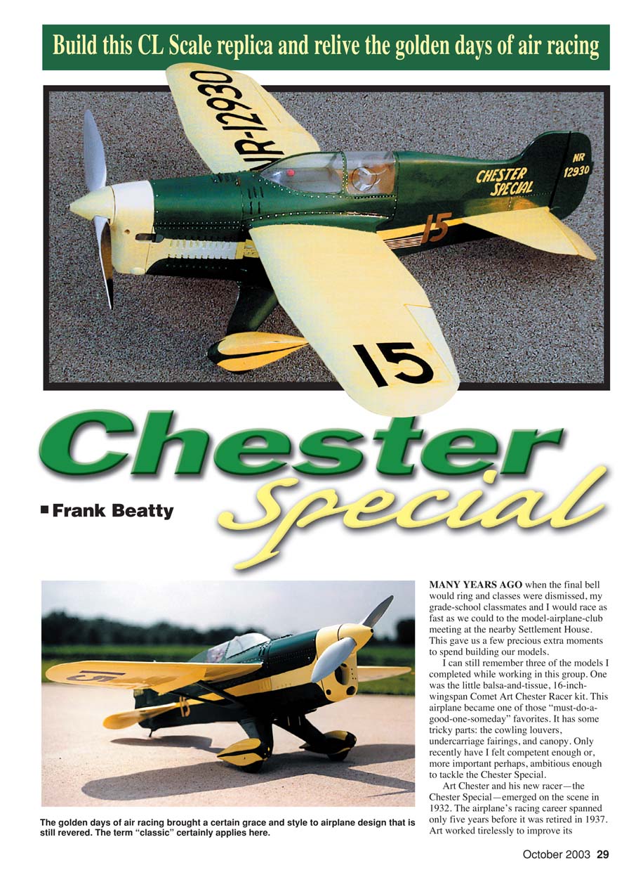
MANY YEARS AGO when the final bell would ring and classes were dismissed, my grade-school classmates and I would race as fast as we could to the model-airplane-club meeting at the nearby Settlement House. This gave us a few precious extra moments to spend building our models.
I can still remember three of the models I completed while working in this group. One was the little balsa-and-tissue, 16-inch-wingspan Comet Art Chester Racer kit. This airplane became one of those “must-do-a-good-one-someday” favorites. It has some tricky parts: the cowling louvers, undercarriage fairings, and canopy. Only recently have I felt competent enough—or, perhaps more important, ambitious enough—to tackle the Chester Special.
Art Chester and his new racer—the Chester Special—emerged on the scene in 1932. The airplane’s racing career spanned only five years before it was retired in 1937. Art worked tirelessly to improve its performance; through the years, almost all of the airplane's components were modified.
He made major changes to the fuselage length and the wing and horizontal tail-surface planforms. He made numerous modifications to the cowling, canopy, and streamlined fairings. In 1936, after a major rebuild that included new fabric and a new color scheme, the little racer was renamed the "Jeep." Owing to Art's efforts, its top speed had been increased from 154 to 253 1/2 mph.
Most good three-views of the Art Chester Racer try to include information about as many of these modifications as possible. This can be daunting to a serious model builder who wants to document and construct an accurate competition model. Photographs are this builder's best friends because a good selection of photos can help him or her sort through all of the confusing and sometimes contradictory material.
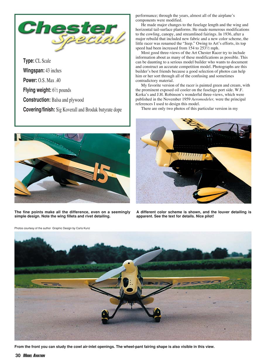
My favorite version of the racer is painted green and cream, with the prominent exposed oil cooler on the fuselage port side. W.F. Kerka's and J.H. Robinson's wonderful three-views, which were published in the November 1959 Aeromodeller, were the principal references I used to design this model.
There are only two photos of this particular version in my reference library, but they did resolve some contradictory marking details in these sets of drawings. I found those photos in the April 1996 Skyways and The Golden Age of Air Racing, Volume 2. I obtained a color photo, probably artist-tinted, from the January 1935 Popular Aviation. I am not sure that anyone can say with certainty what shades of green and cream were used on the full-scale airplane. I selected Brodak Piper Cream and Forest Green for this model because they complement each other nicely and were readily available.
I built the model to a scale of 2 1/2 inches = 1 foot. The wingspan is 43 inches, and the length is 38 inches. Power is an O.S. .40. The model features a Roberts three-wire system to operate an engine throttle. I corrected initial pitch-sensitive flight characteristics by adding weight to the model's nose. It flies smoothly, can be set up for good landing approaches, and has good ground handling.
CONSTRUCTION
It is my practice to break a model project into smaller subassemblies, which are easier to handle and fabricate. They can also be sanded and finished up through the final primer coats, then set aside until final assembly of all components.
Read through the entire construction sequence. If you agree with the methodology, follow it. No serious problems are likely to occur if you follow your favorite construction practices. After all, there is more than one way to do things.
Note: CyA = cyanoacrylate glue (superglue).
Wing
I constructed the wing on my board of choice for structures such as this: a Paul Guillow 1 x 14 x 48-inch balsa workboard, which boasts a flat work surface and readily accepts pins for holding structures firmly in position.
- Make the 1/8-inch plywood bellcrank mounting platform. Bolt the bellcrank to the plate and check for freedom of movement. When you're satisfied, remove the bellcrank from the plate and set these parts aside.
- Cut the 1/8-inch basswood spars. Cement nine temporary rectangular 1/8-inch balsa shims to each spar, and trim them to be parallel to each spar's top surface. Pin the plans and waxed-paper overlay to the building board. Carefully locate and pin the spars in place. Epoxy the bellcrank mounting platform between the spars.
- Fit the ribs into the spars' interlocking slots and set them flush with the spar top surfaces. Slip the four 1/8 x 1/2-inch balsa leading-edge (LE) pieces into the slotted rib LEs. Shim and pin them firmly into position.
Consider using trailing edges with a 1/32-inch plywood core. Knife-edged trailing edges with this construction nicety are less susceptible to dings. Tape together four pieces of 1/8 x 3/4-inch balsa. Cut all notches, then separate the parts. CyA a 1/32 x 7/8-inch plywood piece between each pair of these pieces. The protruding plywood flange slides into slots in the ends of the ribs. CyA all joints. Fit and glue the aileron spars to the assembly.
Block-sand the entire structure before you begin covering with sheet. Work from the center-section out and sheet the LEs. Sheet-cover the wing center-section, then capstrip all ribs with 1/16 x 3/16-inch balsa strips. The large cutout area in the wing center-section is intended to leave the cockpit area clear for super detailing.
Lift the wing assembly from the building board. It is fairly flexible at this point. Trim the temporary balsa shims from the spars. Epoxy 2 ounces of lead weight into the starboard wingtip (see plans). Make six 1/4-inch sheet-balsa cradles (see plans sheet 2), and pin them to the building board at rib stations C, I, and P. Settle the wing assembly into the cradles and pin them securely.
Apply sheet covering and capstrips similar to the way you did it to the top surfaces. Note that an area between ribs H and I is sheet-covered to accommodate installation of the balsa strut fairings later.
Lift the wing from the building board. The structure is quite stiff. This somewhat elaborate procedure has produced the straightest wing I have ever built.
Cement 3/8-inch balsa strips to the framework. Construct the aileron framework and temporarily tack-glue it to the wing. Carve and sand the entire wing smooth. Drill and install brass-tubing leadout guides in the port wingtip. Drill aileron spars for six 1/8-inch-diameter dowel locator pins, and cut the ailerons separate from the wing.
Bolt the bellcrank assembly, fitted with 3/64-inch-diameter leadout wires, in place. Bend loops in the leadout-wire ends. Sand the wing and aileron assembly to satisfaction, and cover it using Sig Stix-It and Sig Koverall.
Fabricate large balsa strut fairings and epoxy them to the wing. The wing and ailerons can be finished all the way through final primer coats using your favorite methods, then set them aside until final assembly.
Stabilizer, Elevators, and Rudder
You can get strong, scale-like fabric-covered tail surfaces by building them around an internal 1/64-inch plywood core. You can use a 3/8-inch-diameter Brad Point or Forstner drill bit to drill desired lightening holes in the 1/64-inch plywood. Those drill bits' sharp, knifelike outer rims can cut perfect holes without shredding or tearing the thin plywood.
- Make your 1/64-inch plywood cores. Cement the balsa ribs and spars to them.
- Soak 1/16 x 1/4-inch balsa strips in household ammonia, and bind the wet strips around these structures. When dry, CyA the laminations to these structures.
- Locate the control horn and epoxy it to the elevators. Cut slots in the plywood for Robart hinges, and reinforce the cutouts with balsa rectangles.
Carve and sand all parts to satisfaction. Cover with Sig Stix-It and Sig Koverall. You can finish these parts all the way to the final primer coats, then set them aside.
Undercarriage
- Make a 1/8-inch plywood undercarriage mounting plate. Bend up two 5/32-inch-diameter music-wire struts. Bind the struts to the plate with thread and epoxy. Bind the strut free ends with soft copper wire and solder. Solder 0.010 x 1 3/4-inch-diameter brass disks to the axle. Cement formers 3A, 5A, and 7A to the mounting plate, then plank the structure with 1/8 x 3/8-inch balsa strips.
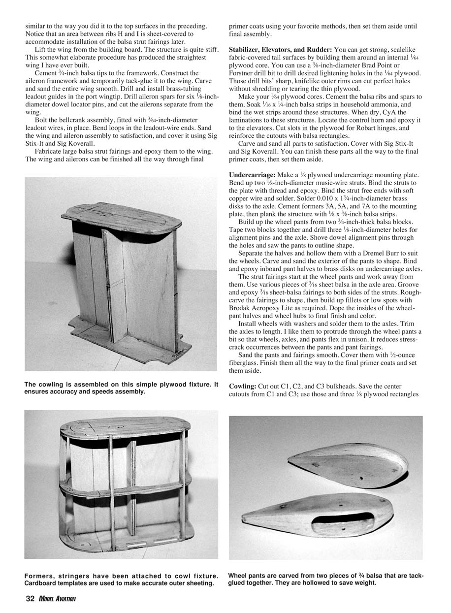
- Build up the wheel pants from two 3/4-inch-thick balsa blocks. Tape two blocks together and drill three 1/8-inch-diameter holes for alignment pins and the axle. Shove dowel alignment pins through the holes and saw the pants to outline shape.
- Separate the halves and hollow them with a Dremel Burr to suit the wheels. Carve and sand the exterior of the pants to shape. Bind and epoxy inboard pant halves to brass disks on undercarriage axles.
The strut fairings start at the wheel pants and work away from them. Use various pieces of 3/16-inch sheet balsa in the axle area. Groove and epoxy 3/16-inch sheet-balsa fairings to both sides of the struts. Rough-carve the fairings to shape, then build up fillets or low spots with Brodak Aeropoxy Lite as required. Dope the insides of the wheelpant halves and wheel hubs to final finish and color.
Install wheels with washers and solder them to the axles. Trim the axles to length. I like them to protrude through the wheel pants a bit so that wheels, axles, and pants flex in unison. It reduces stress-crack occurrences between the pants and pant fairings.
Sand the pants and fairings smooth. Cover them with 1/2-ounce fiberglass. Finish them all the way to the final primer coats and set them aside.
Cowling
- Cut out C1, C2, and C3 bulkheads. Save the center cutouts from C1 and C3; use those and three 1/8-inch plywood rectangles to make a simple plywood fixture to assemble the cowling bulkheads (see plans sheet 3). Use the fixture to assemble the original bulkheads (C1, C2, and C3) and six 1/8 x 1/4-inch basswood stringers (C4 through C7) to align all parts before applying CyA to all joints.
- Make cardboard patterns and use them to cut out 1/32-inch plywood cowling side panels. Lay out louver cutout patterns on each panel. Note that the lower louver layout is different on each side. Use a #11 X-Acto knife to cut out all louvers, then CyA the panels to the cowling formers.
- CyA 3/32 x 1/4-inch basswood strips behind each louver opening. Use an X-Acto knife, needle files, and sandpaper to carve and smooth each opening. When you're satisfied with the result, plank the cowl top and bottom with 3/32 x 3/8-inch basswood strips.
Alternate methods of simulating louver details include making them from fiberglass or using a metal die and stamping the louvers in soft sheet metal. I am more comfortable working with wood, so I used that medium.
The nose block is made from a basswood block. Cut the block to the front, side, and top outline, and tack-glue it to the cowling. Shape and fair it to blend into the cowling, leaving a little excess at the spinner area for future fitting.
Cut the nose block free from the cowling, and use a Dremel Burr to hollow it out to approximately 1/8-inch wall thickness except in the areas where the cowl hold-down bolt will be. Drill or cut out all scale cooling air holes and the propeller-shaft access hole. Lay out and drill four 7/16-inch-diameter holes in the cowl's lower starboard side for dummy exhaust stacks. Set the cowl aside for final fitting to the fuselage.
Fuselage
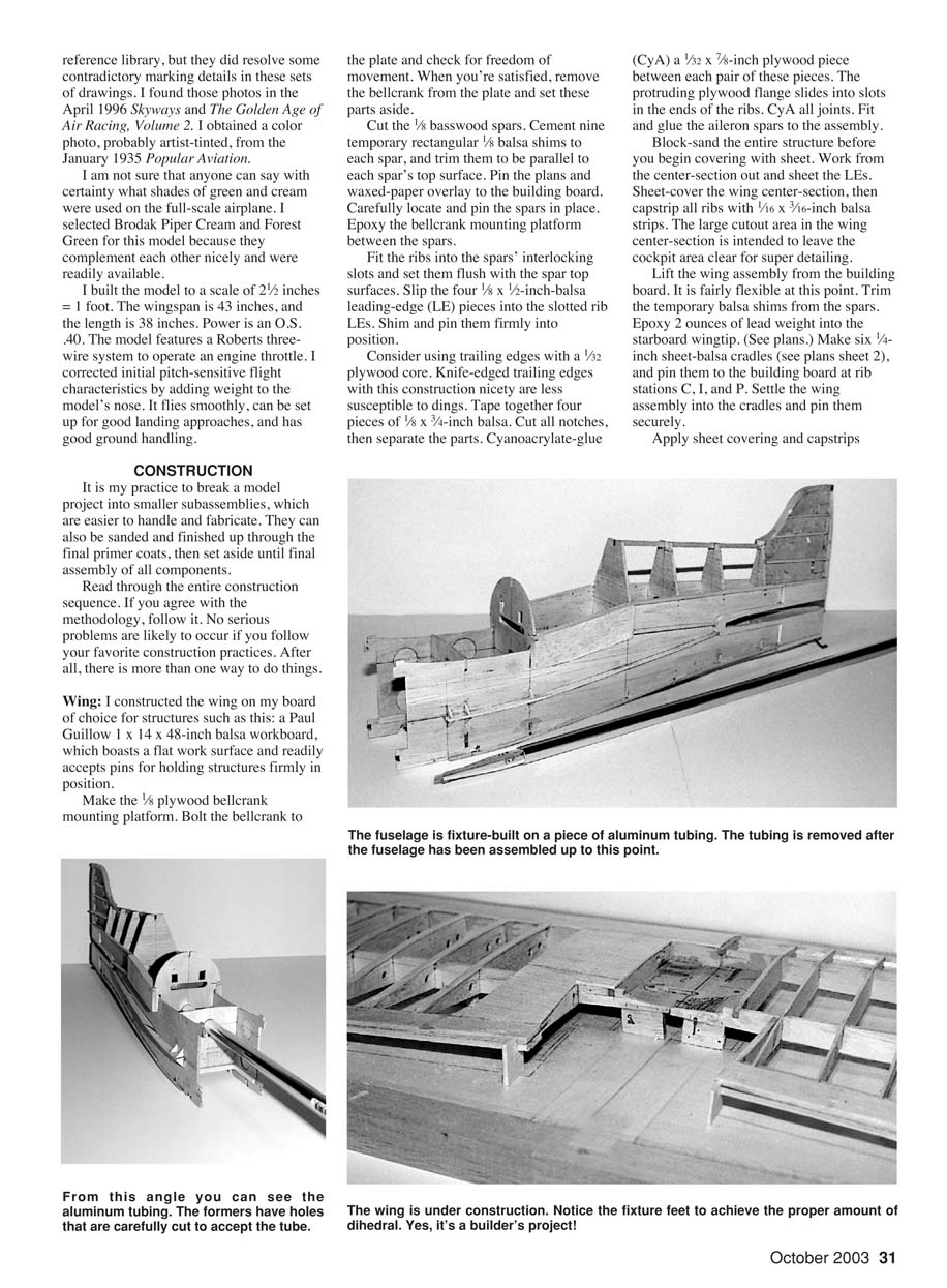
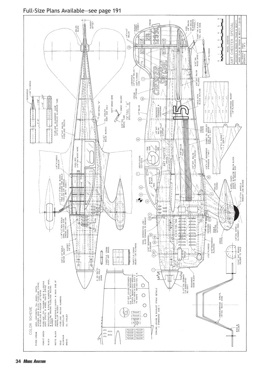
- Obtain a piece of 3/4-inch-diameter, 30-inch-long Reynolds aluminum tubing. Make a plug assembly (see plans details) and CyA it into the tubing end. This plug end tab will slip into a slot in bulkhead 12 at the narrow fuselage tail end.
- Cut out the 1/16-inch sheet-balsa fuselage crutch members and all bulkheads. Cement 1/16-inch plywood doublers to the fuselage crutch members. Mark centerlines on the crutch members and on all bulkheads. Tabs on each bulkhead will interlock with corresponding cutouts or slots in the side crutch members.
- Carefully align and CyA interlocking bulkheads 3, 5, and 7 to the fuselage crutch members. Slide the tubing guide through these bulkheads, then slip remaining bulkheads 8, 9, 10, 11, and 12 onto the guide. With the guide properly located, pin and CyA these bulkheads to the crutches. This should result in a straight fuselage crutch assembly.
Cement 1/2 x 1-inch balsa blocks to the firewall and crutch joint area (these will be partially carved away later to form scale cooling air passageways). Make the tailskid, and mount and CyA it to the crutch.
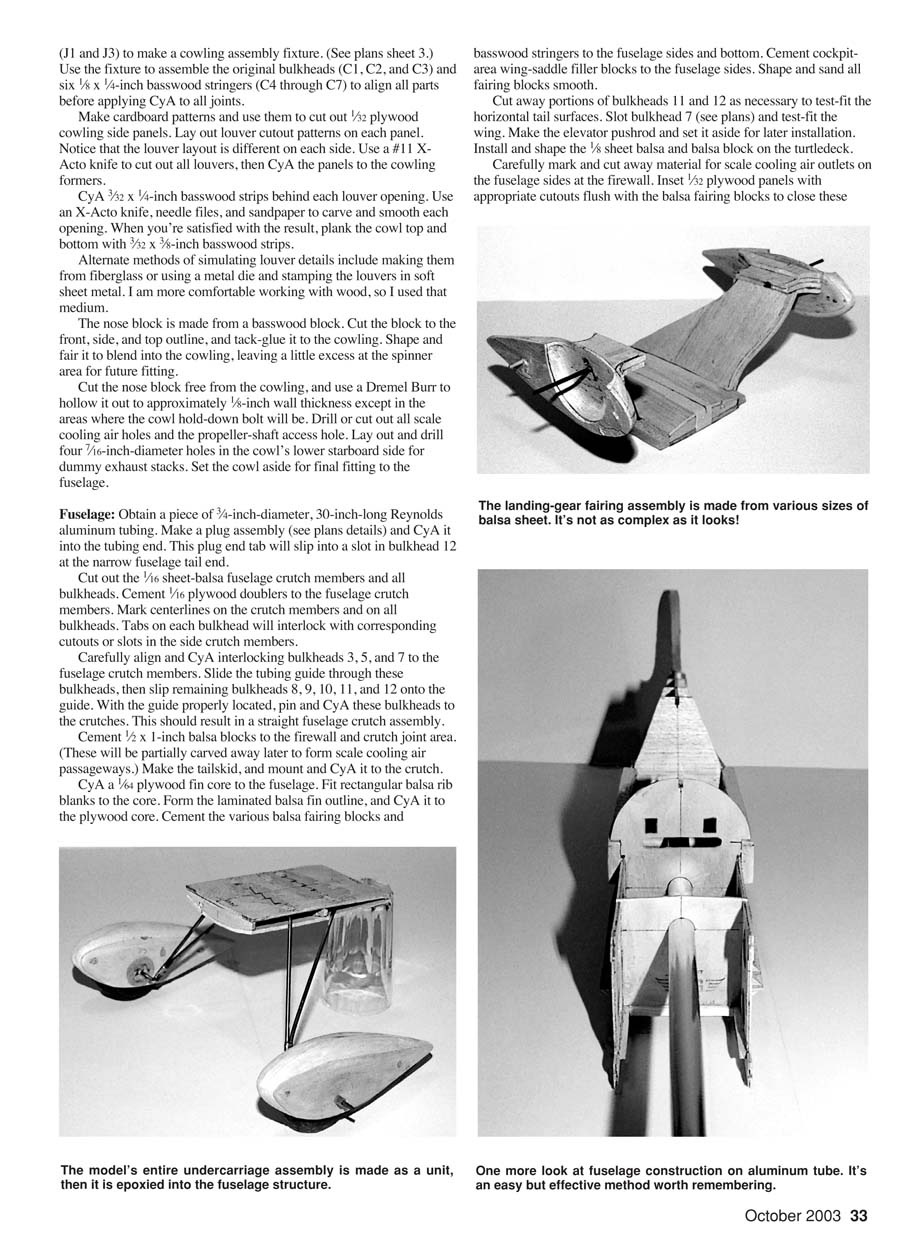
CyA a 1/4-inch plywood fin core to the fuselage. Fit rectangular balsa rib blanks to the core. Form the laminated balsa fin outline, and CyA it to the plywood core. Cement the various balsa fairing blocks and basswood stringers to the fuselage sides and bottom. Cement cockpit-area wing-saddle filler blocks to the fuselage sides. Shape and sand all fairing blocks smooth.
Cut away portions of bulkheads 11 and 12 as necessary to test-fit the horizontal tail surfaces. Slot bulkhead 7 (see plans) and test-fit the wing. Make the elevator pushrod and set it aside for later installation. Install and shape the 1/8-inch sheet balsa and balsa block on the turtledeck.
Carefully mark and cut away material for scale cooling air outlets on the fuselage sides at the firewall. Insert 1/32-inch plywood panels with appropriate cutouts flush with the balsa fairing blocks to close these openings.
Make the 3/8 x 1/2-inch engine mount and gusset assemblies with cowling-bolt-down blind nuts installed. Temporarily fit the mounts in the fuselage, drill and set the blind nuts, and bolt the engine to the mounts. Install the throttle crank and its mounting plate. Remove the engine and mounts, and set them aside.
Epoxy the undercarriage assembly into the fuselage. Tidy up the openings or gaps around the gear with balsa scraps and Aeropoxy Lite. With the fuselage assembled, cover it with Sig Stix-It and Sig Koverall, starting at the bottom, working up the sides to the wing cutout, and overlapping at the top of the turtledeck.
Fit the wing and stabilizer to the fuselage, check them for alignment, and epoxy them in permanently. Install the elevators with the pushrod and connect to the bellcrank. Epoxy engine mount/gusset assemblies into the fuselage.
Install a balsa dummy-pilot support and bulkheads 4 and 6, which are glued to the top of the wing center-section planking. Plank the fuselage top and cut the cockpit opening. Fit and carve balsa fillets at the wing. Cover any bare wood with fiberglass, silk, or Koverall—your choice.
Before installing the canopy, finish the cockpit interior and finish the top of the fuselage with matte black. The scale instrument panel shown on the plans is too deep by 1/2 inch because of the dummy-pilot support's location. I compromised by using the top half of the panel with three large instruments in my model.
I worked according to Don Tynpon's excellent videotape How to Paint Pilot Figures to paint the 2-1/2-inch scale Williams Bros. pilot before I installed it in the cockpit. Don't forget to make and install the dummy gas cap before you close the area.
Form the canopy from a carved-balsa master mold and a 4-inch-deep forming box with a 1/4-inch plywood cutout, as you may have seen illustrated in magazine articles. Heat 1/16-inch-thick Perspex acrylic sheet to 350°F and "pull" the canopy. Trim the canopy to fit and cement it to the fuselage with Testors plastic cement. Mark off the areas that will remain clear, and create small fillets around the canopy's perimeter with Aeropoxy Lite.
Install the fuel tank and associated filler pipes. Bolt the engine in place and fit the throttle linkage. Install a remote glow-plug connector; access to the remote glow plug is through a large nonscale hole in the cowling bottom.
Bolt the cowling in place and fair it to the spinner if you haven't already. Locate and drill out all needle valve, muffler, and muffler-fastener access holes. Remove the cowl and cover it with 1/2-ounce fiberglass.
Install details such as the protruding louvers, dummy air scoop, and tailskid fairing. Fabricate wing-lift struts from basswood, check them for fit, and cover them with fiberglass and primer.
Finishing: It is good practice to use one brand of paint products throughout the finishing process to reduce the possibility of incompatible products causing cracks, peeling, or other surface problems. I used Brodak thinners, primer, and color dopes. I thinned all primer, clear, and color dopes 50% or more.
At this point all structures are complete, with covering materials and some primer on surfaces that will seem fairly smooth. The model should be finished in a way that adds minimum excess weight.
- Spray silver dope over all surfaces. Any rough spots that need attention will be highlighted and will shine like a neon light. Instead of adding unnecessary weight by spraying additional coats on the entire model, spot-spray and wet-or-dry sand alternate coats of silver and filler on the rough areas that need attention until the entire model has a smooth base for color-coat applications.
- Spray two to four coats of Piper Cream on the appropriate areas. Mask as required and spray two to four coats of Forest Green on the fuselage, undercarriage, and struts. Mask again as required and spray the black and gold registration and racing numbers on the wing and fuselage.
Various types of pens can be used to apply surface detailing. Some are easy to smear, so as you work, protect completed areas with a light dusting of clear dope, then move on to the next area.
I used a black TopFlite MonoKote Panel Line Pen, a black Sanford Sharpie Permanent Marker, and a Pilot Silver Marker. These pens work best on smooth doped surfaces after the areas have been rubbed lightly with talcum powder.
Panel lines can be simulated with black striping tape or black pens. Screw heads, rivets, and other fasteners are simulated with silver dots. I drew the canopy ventilation openings with a black pen because I feared that debris would be trapped in the cockpit if these openings were cut out.
Use a credit card held low at an oblique angle to scrape off any ridges left by the masking tape. Spray on roughly a half dozen coats of clear dope. Sand the entire model with increasingly finer grades of wet-or-dry paper, finishing in the 600–1,200 range. Complete the job with rubbing compound and wax.
Propeller: Even the neatest scale model will look unfinished if it isn't fitted with a scale propeller. Glue together six 3/16 x 1 1/4 x 14 1/2-inch basswood blanks, drill them for the propeller shaft, and saw them to outline shape. I used a Prather Prop Pitch Gauge to carve accurate blades. The propeller is too thick to accommodate the propeller nut and washer, so cut the hub area back to 1/2-inch deep.
Paint the propeller with aluminum-colored dope. Paint the back sides of the blades matte black.
Final Assembly
Four dowels anchor the left struts to the wing and fuselage. The outboard strut ends are located with dowels and predrilled holes in the wing-strut fairing blocks. Two 5/16-inch-diameter dowels anchor the strut at the fuselage longeron line.
Short lengths of 7/16-inch-diameter brass tubing are installed in the cowling dummy exhaust-stack openings.
Sweat-solder lengths of soft brass wire into each end of six pieces of 3/32-inch-diameter brass tubing. Space and align the tubing carefully, and sweat-solder a 5/16-inch-wide brass strip at roughly the middle of these pieces. Bend the soft wire at right angles.
Drill holes in the fuselage dummy oil-cooler supports that will align with those 12 wires. Press the wires into the holes and CyA them securely. Two pins through the central brass strip will help secure this assembly.
Install the rudder using Robart hinges and epoxy. Offset the rudder approximately 1/4 inch. A dot of CyA to the hinge point will lock the rudder in position.
You can form a small dummy air scoop from sheet styrene the same way you made the canopy. Trim the scoop to size and cement it to the canopy starboard side.
Install the ailerons using 1/8-inch-diameter birch dowels and epoxy. I like to incorporate 1/16 inch of offset in each aileron so that the model will roll away from the pilot to maintain positive line tension.
Flying
Trying to start inverted engines that are enclosed in cowlings that make it difficult or impossible to choke the engines gives me a fit. I modified an expanded-polystyrene-foam ice cooler to provide a cradle to support the Chester Special in an inverted position.
After I start the engine, it is simple to flip the model upright and get on with the flight. This procedure takes the pressure off when I'm trying to comply with that three-minute time limit at a contest site.
Before test-flying the model, I checked it for balance by suspending it by its wingtips at a point in-line with the LE sheet covering line. The model hung level, which indicated that it verged on being tail-heavy.
Nevertheless, I flew the model that way. The first flight proved pitch-sensitive and was erratic. The airplane was difficult to fly smoothly, and it was difficult to set up for a satisfactory landing approach. I was happy when I executed a safe landing after a few laps.
The model's nose hung down roughly 5° after I epoxied 5 ounces of lead into the cowling and installed a 2-ounce heavy brass propeller nut. Subsequent flights were tame; smooth touch-and-gos and landings became routine.
I had been extremely pleased with the true-to-scale cooling air openings and vents that were incorporated into this model. However, the engine was not getting enough cooling, was running too hot, and was plagued with unplanned engine stoppages.
I cut a 1/4 x 2-inch nonscale opening into the cowling bottom. Friends suggested that the propeller was working the engine too hard, so I modified the propeller to 11 inches in diameter with 5 inches of pitch. These measures solved the engine-cooling problems.
To improve the model's appearance I replaced the large factory muffler with a tongue-type muffler. I epoxied 2 ounces of lead into the cowling to compensate for the weight difference. The tongue-muffler idea didn't work out, and I reinstalled the original muffler. The 2 ounces remained in the cowling.
A nice-flying model became a very nice-flying model. This vividly illustrated how balance can affect a model's performance.
More than 60 years had elapsed between construction of the two versions of the Art Chester Racers that I built. They are two models I will never forget.
Frank W. Beatty 2608 Pontoon Rd. Granite City, IL 62040
Transcribed from original scans by AI. Minor OCR errors may remain.

