
CL Aerobatics
I remember when we used to build our models "in the air." If we were lucky, there was an article in one of the current model magazines that had instructions on how to build and align a model.
The good kits, such as the Veco line, had illustrated assembly procedures that worked well in conjunction with the early prefabrication. Even these early kits had to be constructed "in the air" using the model cements of the time, such as Ambroid.
Assembling the components depended on the accuracy of the cutouts and whether the wood had warped after the cutting. No wonder we used to consider ourselves lucky to have one in two or three models that flew really well!
Remember when the "Detroiter" I-beam wing design came on the scene? They were beautifully constructed and flew well. A possible reason they flew as competitively as they did was their method of construction.
The early I-beam models were among the first, if not the first, Stunt designs that incorporated alignment features in the construction. Since the wing and fuselage were assembled as a unit, the accuracy of the heart of the model was assured.
For a complete, step-by-step video tutorial on how to construct an I-beam wing, conducted by master builder Bill Werwage, contact Robin's View Productions. (All addresses for sources mentioned are listed at the end of this column.)
The next big advance in construction for the Stunt community was the advent of the foam wing. For the first time, many fliers had truly accurate wings available as a basis for a good-flying model.
Almost overnight, the number of excellent models multiplied, as did the superior finishes, because of the solid, true sheeted surface.
By now you might be wondering where I'm going with this discussion. The subject was prompted by a recent building session in which I constructed a fuselage crutch. I used an adjustable fixture to align the various formers.
Fuselage Fixtures:
Typical of the commercial designs are those with flat surface bases with heavy reinforcement and multiple, adjustable uprights to hold the formers in position.
Fixtures of this design offer good flexibility; as most Stunters are designed with a fuselage crutch that has a reference line parallel to the thrustline.
Jim Hunt made the fixture I use, and, sadly, it is no longer available. If you can get someone to part with one, buy it! A similar fixture is available from C.F. Smitherly. These are robust and very useful. I recommend them.
Of course, there are other approaches to fuselage fixturing. The Al-Rabe style serves very well with the semiscale model that has a very large cross section.
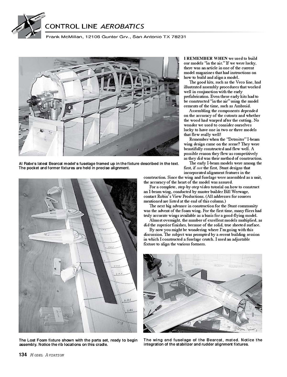
Al's fixture uses "pockets" that hold the formers in exact three-dimensional location: fore/aft, side-to-side, and up/down. With the formers accurately positioned, interior structure is installed and the exterior skin applied.
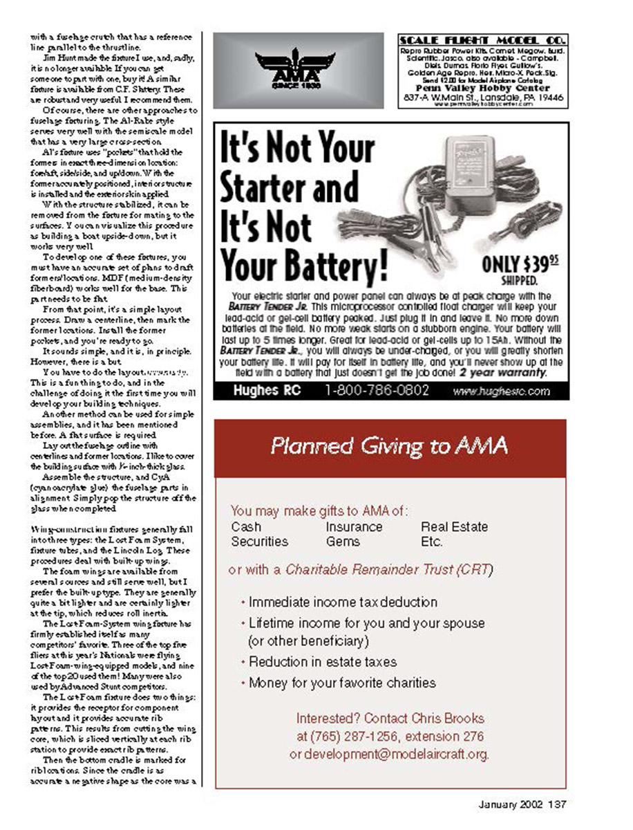
With the structure stabilized, it can be removed from the fixture for mating to the surfaces. You can visualize this procedure as building a boat upside-down, but it works very well.
To develop one of these fixtures, you must have an accurate set of plans to draft former locations. MDF (medium-density fiberboard) works well for the base. The parts need to be fitted.
From that point, it's a simple layout process. Draw a centerline, then mark the former locations. Install the former pockets, and you're ready to go.
It sounds simple, and it is, in principle. However, there is a but.
You have to do the layout, and this is a fun thing to do, and it is the challenge of doing it the first time you will develop your building techniques.
Another method can be used for simple assemblies, and it has been mentioned before. A flat surface is required.
Lay out the fuselage outline with centerline and former locations. I like to cover the building surface with 1/8-inch-thick glass.
Assemble the structure, and CYA (cyanoacrylate) glue the fuselage parts in alignment. Simply pop the structure off the glass when completed.
Wing/semiscale fixtures generally fall into three types: the Lost-Foam System, fixture tube, and the Lincoln Logs. These procedures deal with built-up wing rigs.
The foam wings are available from several sources and still serve well, but I prefer the built-up type. They are generally quite a bit lighter and are certainly lighter at the tip, which reduces roll inertia.
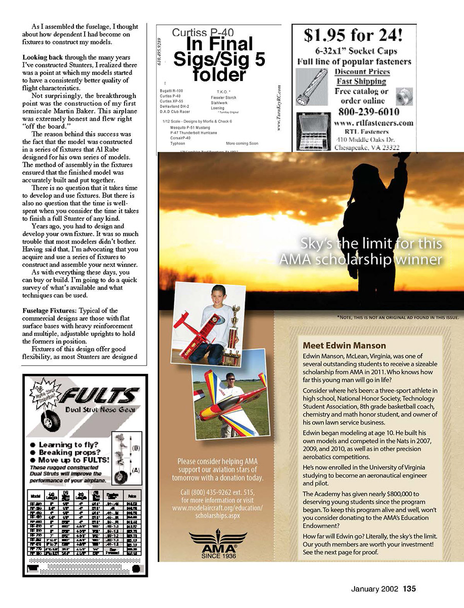
The Lost-Foam-System wing fixture has firmly established itself as a competitor favorite. The tree of the top ribs sets the rib stations, and the top and bottom sanded ribs are held on the tree exactly where they belong. The Lost-Foam-System uses a main spar and a pair of pins that register the rib positions longitudinally. The system allows the wing to be built strongly and accurately.
It provides the necessary support and alignment and can be used for multiple wing panels by duplicating the tree. If you decide to use the Lost-Foam-System, make sure your plans match the fixture spacing.
If not, you will have to redrill the tree or change the station positions slightly.
The important things are accuracy and patience. Take your time; do the layout carefully; spot-check your work. You'll be rewarded with a well-built model that flies true.
CL Aerobatics
positive shape, the ribs fit the center exactly and guarantee an accurate wing.
With the Lost-Foam System you can also accurately construct wing panels with included dihedral and build multiple-spar wings, such as those required for a scale Mustang.
If you're not sure about how this process works, send $2 to Robin's View Productions; they will send you a complete instruction manual for the Lost-Foam System so you can study the procedure before trying it.
Another procedure is the fixture-tube method. There have been several commercial versions, but I haven't seen any advertised for some time. Al taught me how to do it, and it works well.
Aircraft aluminum tubing, usually 1 inch in diameter, serves as the alignment medium. The ribs must be slotted and the holes positioned to align the structure properly. Dihedral can easily be incorporated.
The ribs slide over the tubes with the tubes supported on four equal-height pedestals. By sighting down the interior of the tubes, you can achieve alignment to a few thousandths of an inch.
The two tubes are typically separated fore and aft by four or five inches. In the latest version, Al has a third tube set between the main twin tubes and parallel to the trailing edge.
I observed construction of the new Beech using the three tubes, and the third makes for a much more rigid setup.
There is a newcomer on the scene, and that's Tom Moore's Lincoln Log method. It involves notched fixture blocks that hold the leading and trailing edges in position relative to a flat surface.
The leading/trailing edges are three pieces, with a center protruding into the rib to center it. The overall assembly of the wing requires a fixture to hold the leading and trailing edge blocks in position.
This is also a proven method, and it works well. You can purchase it for any wing from Tom's Building Service.
The methods I've described serve well to construct wings and fuselages.
If you haven't used fixtures such as this, you certainly need to explore the various types and stick with the one you feel most comfortable with. Your models will be much better.
In columns to come, I'll look at complete airframe-assembly fixtures.
Sources:
C.F. Sherry Co. 2101 Locust Ave. New Albany IN 47150 (812) 948-9167
Robin's View Productions Box 68 Stockertown PA 18083 (610) 746-0106
Tom's Building Service 327 Pueblo Pass Anniston AL 36206 (256) 820-6970
Transcribed from original scans by AI. Minor OCR errors may remain.

