

Electric power conversion
by Bob Hunt [email protected]
It's time to start the project airplane I mentioned in my last column, which will take advantage of the E-flite Power 15 motor (or an equivalent motor). Such a model should be easy to fly, inexpensive, and could be a competition model as well as an advanced CL aerobatics trainer. The subject model is Bill Werwage's Classic Stunt-legal Vulcan. AMA's Plans Service is the plans source for anyone who might want to build one.
Converting a glow design of any size to electric power is not difficult. You first need to establish the size of the motor to be used, the required ESC, timer, and battery package, and then redesign the structure of the nose of the model to accommodate the electric components.
I know from experience that the Power 15 motor works well in airplanes that range from 480 to 560 square inches and weigh between 38 and 50 ounces including the battery. The lower end of the airplane size yields the best performance with this setup, provided it is built correspondingly light. The Vulcan has a wingspan of 50.25 inches and a 500-square-inch wing area, placing it nicely in the sweet spot.
Electric motors do not vibrate nearly as much as glow engines do—hardly at all—and put less stress on the model, especially at the nose. This is where you can save a great deal of weight in an electric conversion. This is where we will start on our project.
The glow version of the Vulcan was designed using normal maple engine-mount beams, a tank floor plate and former F-2 at the rear of the tank compartment, with a filler piece between the engine-mount beams to increase rigidity.
In the electric conversion, nearly all of that goes away. The nose of the electric version will consist of:
- a motor mount plate (typically 1/8-inch birch plywood or G-10 material),
- a 1/8-inch birch plywood former installed slightly aft of the motor,
- a Lite Ply former located at the rear of the electronics bay, and
- a 1/8-inch Lite Ply fuselage stiffener plate running between the two formers.
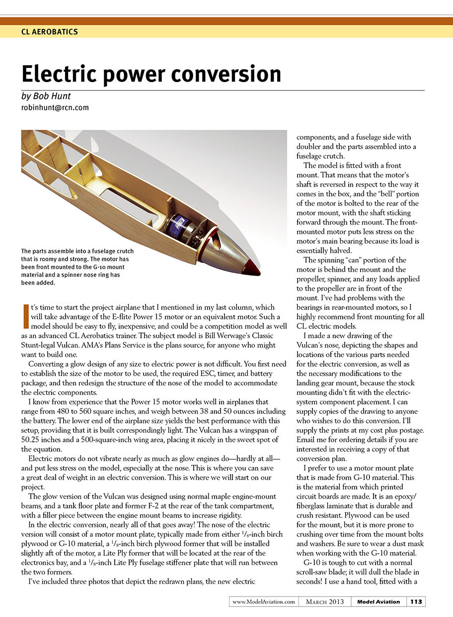
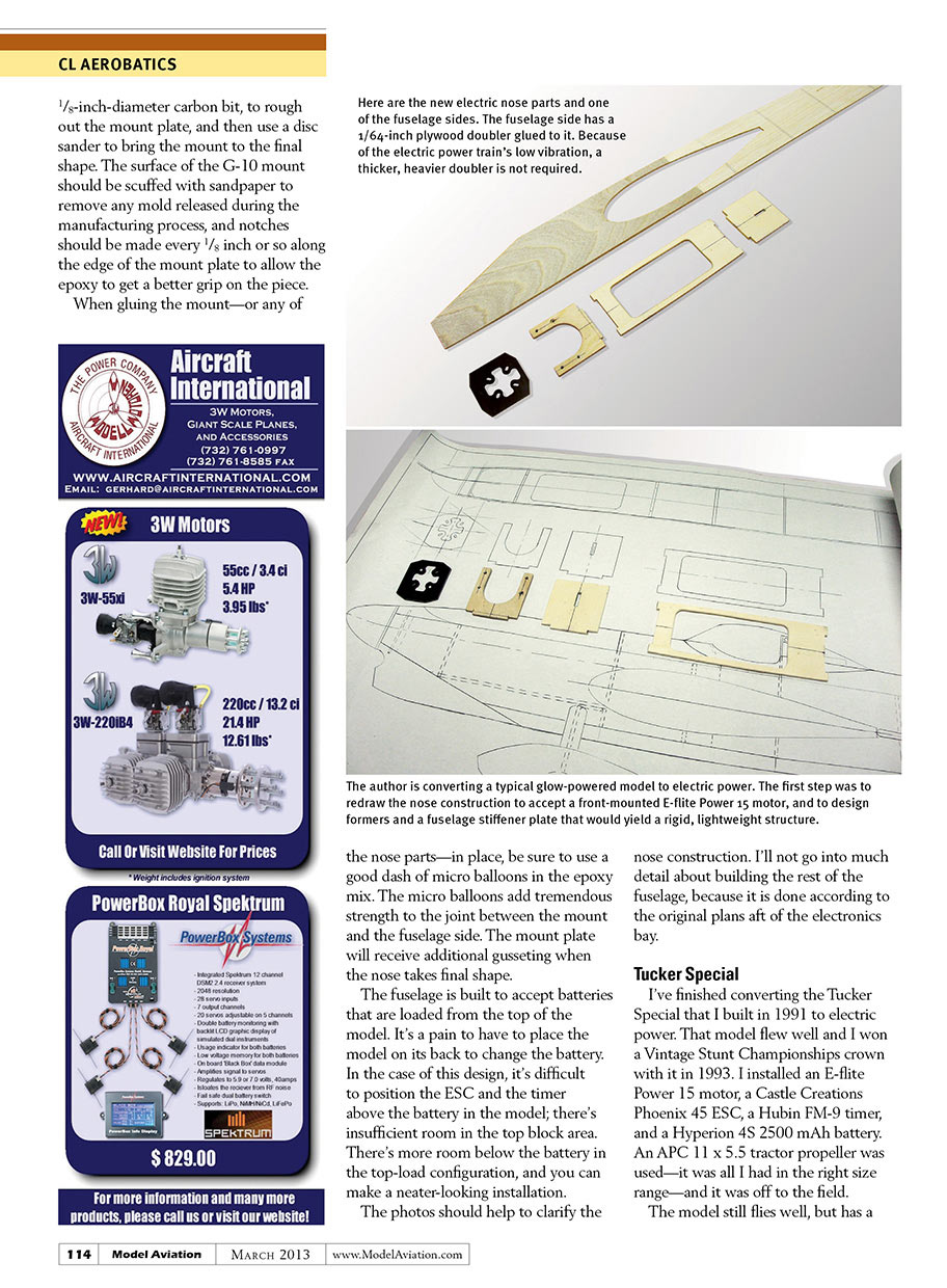
I've included three photos that depict the redrawn plans, the new electric components, and a fuselage side with doubler and the parts assembled into a fuselage crutch.
The model is fitted with a front mount. That means the motor's shaft is reversed relative to how it comes in the box, with the "bell" portion of the motor bolted to the rear of the motor mount and the shaft sticking forward through the mount. Front mounting puts less stress on the motor's main bearing because its load is essentially halved. The spinning "can" portion of the motor is behind the mount while the propeller, spinner, and any loads applied to the prop are in front of the mount. I've had problems with bearings in rear-mounted motors, so I highly recommend front mounting for all CL electric models.
I made a new drawing of the Vulcan's nose, showing the shapes and locations of the various parts needed for the electric conversion, as well as the necessary modifications to the landing gear mount, because the stock mounting didn't fit with the electric-system component placement. I can supply copies of the drawing to anyone who wishes to do this conversion. I'll supply the prints at my cost plus postage. Email me at [email protected] for ordering details.
I prefer to use a motor mount plate made from G-10 material. This is the material from which printed circuit boards are made: an epoxy/fiberglass laminate that is durable and crush resistant. Plywood can be used for the mount, but it is more prone to crushing over time from the mount bolts and washers. Be sure to wear a dust mask when working with G-10. It is tough to cut with a normal scroll-saw blade; it will dull the blade in seconds. I use a hand tool fitted with a 1/8-inch-diameter carbon bit to rough out the mount plate, then finish with a disc sander to bring the mount to final shape. The surface of the G-10 mount should be scuffed with sandpaper to remove any mold release, and notches should be made every 1/8 inch or so along the edge of the mount plate to allow the epoxy to get a better grip.
When gluing the mount—or any of the nose parts—in place, be sure to use a good dash of micro balloons in the epoxy mix. The micro balloons add tremendous strength to the joint between the mount and the fuselage side. The mount plate will receive additional gusseting when the nose takes final shape.
The fuselage is built to accept batteries that are loaded from the top of the model. It's a pain to have to place the model on its back to change the battery. In this design, it's difficult to position the ESC and the timer above the battery; there's insufficient room in the top-block area. There's more room below the battery in the top-load configuration, and you can make a neater-looking installation.
The photos should help to clarify the nose construction. I won't go into much detail about building the rest of the fuselage, because it is done according to the original plans aft of the electronics bay.
Tucker Special
I've finished converting the Tucker Special I built in 1991 to electric power. That model flew well and I won a Vintage Stunt Championships crown with it in 1993. For the conversion I installed:
- Motor: E-flite Power 15
- ESC: Castle Creations Phoenix 45
- Timer: Hubsan FM-9
- Battery: Hyperion 4S 2500 mAh
- Propeller: APC 11 x 5.5 tractor prop
The model still flies well but has a slight "hunt" in level flight. I checked the thrustline and found that I'd inadvertently put in approximately 1° of downthrust. I fixed that and am looking forward to my next flight session.
The big surprise was that in a full pattern run it used only 1,350 mAh. I can easily drop to a Hyperion 4S 2100 mAh battery and be safe. With the battery the model weighs 44 ounces. It's going to be a fun airplane when all of the trim bugs are worked out.
Note
In my January 2013 column (page 124) I incorrectly reported that Tom Hamsthire's Gieseke Nobler was powered using a 5S battery. It is actually powered with a 4S LiPo battery. Thanks to Chris B. for catching this error.
Sources
- Precision Aerobatics Model Pilots Association: www.control-line.org
- AMA Plans Service: www.modelaircraft.org/plans/listing.aspx
Transcribed from original scans by AI. Minor OCR errors may remain.

