
The Vulcan’s battery mount
By Bob Hunt
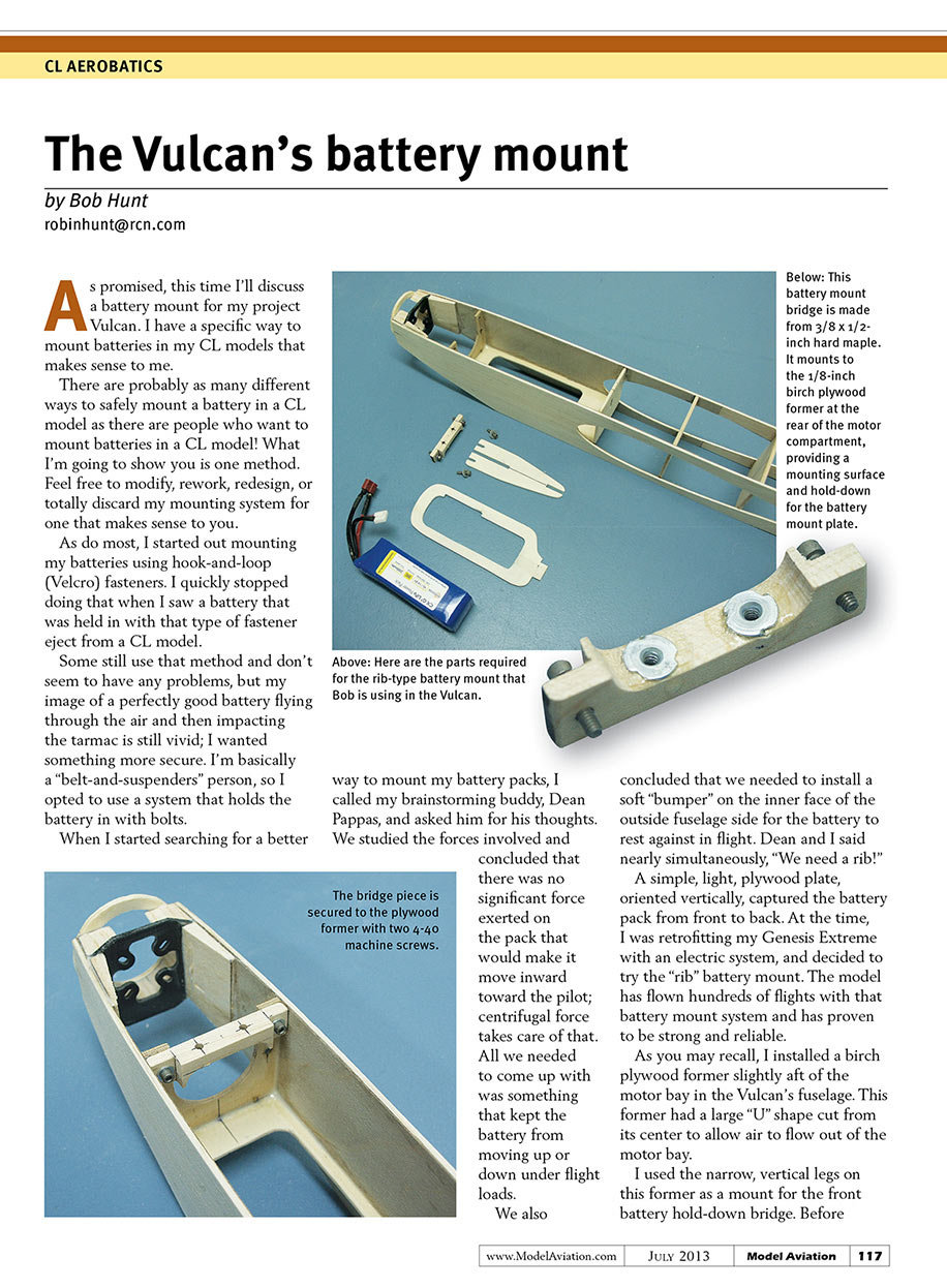
As promised, this time I’ll discuss a battery mount for my project Vulcan. I have a specific way to mount batteries in my CL models that makes sense to me.
There are probably as many different ways to safely mount a battery in a CL model as there are people who want to mount batteries in a CL model. What I’m going to show you is one method. Feel free to modify, rework, redesign, or totally discard my mounting system for one that makes sense to you.
As with most, I started out mounting my batteries using hook-and-loop (Velcro) fasteners. I quickly stopped doing that when I saw a battery that was held in with that type of fastener eject from a CL model. Some still use that method and don’t seem to have any problems, but my image of a perfectly good battery flying through the air and then impacting the tarmac is still vivid; I wanted something more secure. I’m basically a “belt-and-suspenders” person, so I opted to use a system that holds the battery in with bolts.
When I started searching for a better way to mount my battery packs, I called my brainstorming buddy Dean Pappas and asked him for his thoughts. We studied the forces involved and concluded that there was no significant force exerted on the pack that would make it move inward toward the pilot; centrifugal force takes care of that. All we needed to come up with was something that kept the battery from moving up or down under flight loads. We also concluded that we needed to install a soft “bumper” on the inner face of the outside fuselage side for the battery to rest against in flight. Dean and I said nearly simultaneously, “We need a rib!”
A simple, light plywood plate, oriented vertically, captures the battery pack from front to back. At the time, I was retrofitting my Genesis Extreme with an electric system and decided to try the “rib” battery mount. The model has flown hundreds of flights with that battery mount system and it has proven strong and reliable.
Construction details
As you may recall, I installed a birch plywood former slightly aft of the motor bay in the Vulcan’s fuselage. This former had a large “U” shape cut from its center to allow air to flow out of the motor bay. I used the narrow, vertical legs on this former as a mount for the front battery hold-down bridge.
Before installing the plywood former, I drilled and installed two 4-40 blind nuts on its front face. These allow a custom-made front bridge to be bolted in place and to accept the screws that secure the battery holder. The result is a removable front battery hold-down.
The rib that holds the battery pack can be custom designed to suspend it in the electronics bay (what used to be called the tank compartment) wherever you desire. This system allows you to make several ribs and experiment with battery placement vertically and horizontally within the electronics bay so that you can affect vertical (roll) and horizontal (pitch) CG changes at will.
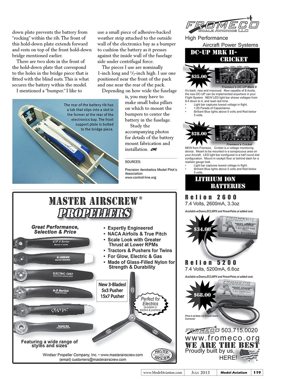
The battery rib is designed with a tab at the rear that fits snugly into a slot in the light plywood former at the rear of the electronics bay. The rib should be custom fitted to the specific battery pack you are using.
Packs of a certain mAh capacity from each of the manufacturers tend to be the same size, so one rib should accommodate all of your packs. You can also experiment with ribs that place the battery in different positions within the electronics bay and then make several ribs—one to fit each of your battery packs—after you find the optimum placement.
Fit and hold-down
The actual fit of the battery inside the rib should be such that the rib is not exerting too much pressure on the outside of the pack, but snug enough so that the pack will not easily move within the rib. A light friction fit is desired. You can use some clear acrylic adhesive to secure the battery within the rib or secure it to the rib with a short piece of 1/2-inch-wide reinforced packing tape.
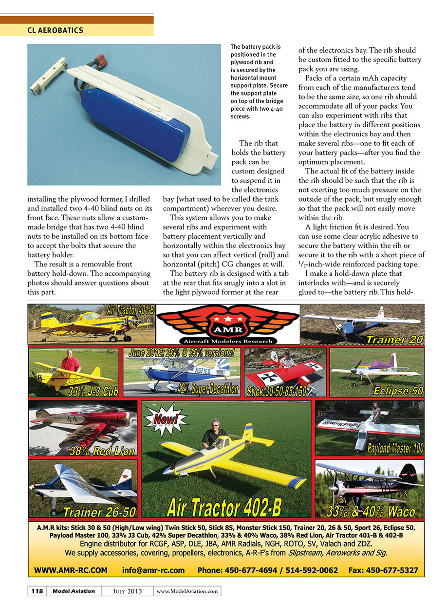
I make a hold-down plate that interlocks with—and is securely glued to—the battery rib. This hold-down plate holds the battery in place and is secured to the front bridge piece with two 4-40 screws. The hold-down plate prevents the battery from “rocking” within the rib. The front of this hold-down plate extends forward and rests on top of the front hold-down bridge mentioned earlier.
There are two slots in the front of the hold-down plate that correspond to the holes in the bridge piece fitted with the blind nuts. This is what secures the battery within the model.
Bumpers
I like to use a small piece of adhesive-backed weather strip attached to the outside wall of the electronics bay as a bumper to cushion the battery as it presses against the inside wall of the fuselage side under centrifugal force.
- Typical bumper size: nominally 1 inch long and 1/2 inch high.
- I use one positioned near the front of the pack and one near the rear of the pack.
Depending on how wide the fuselage is, you may have to make small balsa pillars on which to mount the bumpers to center the battery in the fuselage.
Experiment, test, repeat
Study the accompanying photos for details of the battery mount fabrication and installation. Make multiple ribs to try different placements until you find the optimum balance and fit for your packs.
Sources
- Precision Aerobatics Model Pilot's Association
- www.control-line.org
Transcribed from original scans by AI. Minor OCR errors may remain.

