
Installing a motor mount
by Bob Hunt [email protected]
In my March 2013 “CL Stunt” column, I discussed the front-end design and construction of my electric-powered Vulcan project. This 500-square-inch design is perfect for an E-flite Power 15-size motor and a 2500 mAh 4S battery.
In that column, I touched on the merits of a front-mounted motor and using G-10 material for an actual mount. I did not go into too much detail about the actual installation of the motor mount. Let me rectify that now.
As with any new construction project, better methods come with more experience. After experimenting with motor mounting schemes and techniques, a simple and nearly foolproof method presented itself.
Instead of trying to install the mount plate accurately in the fuselage and then installing and lining up the nose ring for proper spacing, I stumbled onto a method that reverses the process and yields a perfect motor/nose ring alignment, along with the proper amount of motor offset—nearly automatically.
Column space constraints preclude presenting all of the details of mount preparation, but I have prepared an instruction manual that explains the entire process. I will gladly send a PDF of that manual to anyone who requests it. There is no charge; contact me at the email address listed in “Sources,” and ask for the front mount manual.
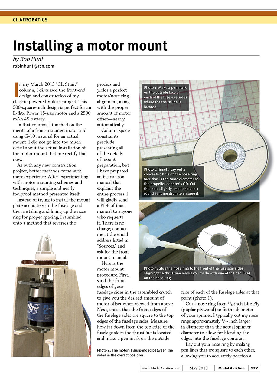
Here is the motor mount procedure. First, sand the front edges of your fuselage sides in the assembled crutch to give you the desired amount of motor offset when viewed from above. Next, check that the front edges of the fuselage sides are square to the top edges of the fuselage sides. Measure how far down from the top edge of the fuselage sides the thrustline is located and make a pen mark on the outside face of each of the fuselage sides at that point.
Cut a nose ring from 1/8-inch Lite Ply (poplar plywood) to fit the diameter of your spinner. I typically cut my nose rings approximately 1/32 inch larger in diameter than the actual spinner diameter to allow for blending the edges into the fuselage contours.
Lay out your nose ring by making pen lines that are square to each other, allowing you to accurately position a concentric hole on the nose ring face that is the same diameter as the propeller adapter’s OD. Cut this hole slightly small and use a round sanding drum to enlarge it.
Glue the nose ring to the front of the fuselage sides, aligning the thrustline marks you made with one of the pen lines on the nose ring.
After you have your mount plate cut to the width required to fit between the fuselage sides, mount the motor to the plate. Hold the fuselage crutch vertically and position the motor and mount plate assembly into the fuselage behind the nose ring.
Put the propeller adapter onto the shaft of the motor and then put the spinner backplate, a propeller (or a spacer that takes the place of a propeller), and a propeller nut onto the shaft and push the motor assembly forward until the shaft bottom is in the adapter.
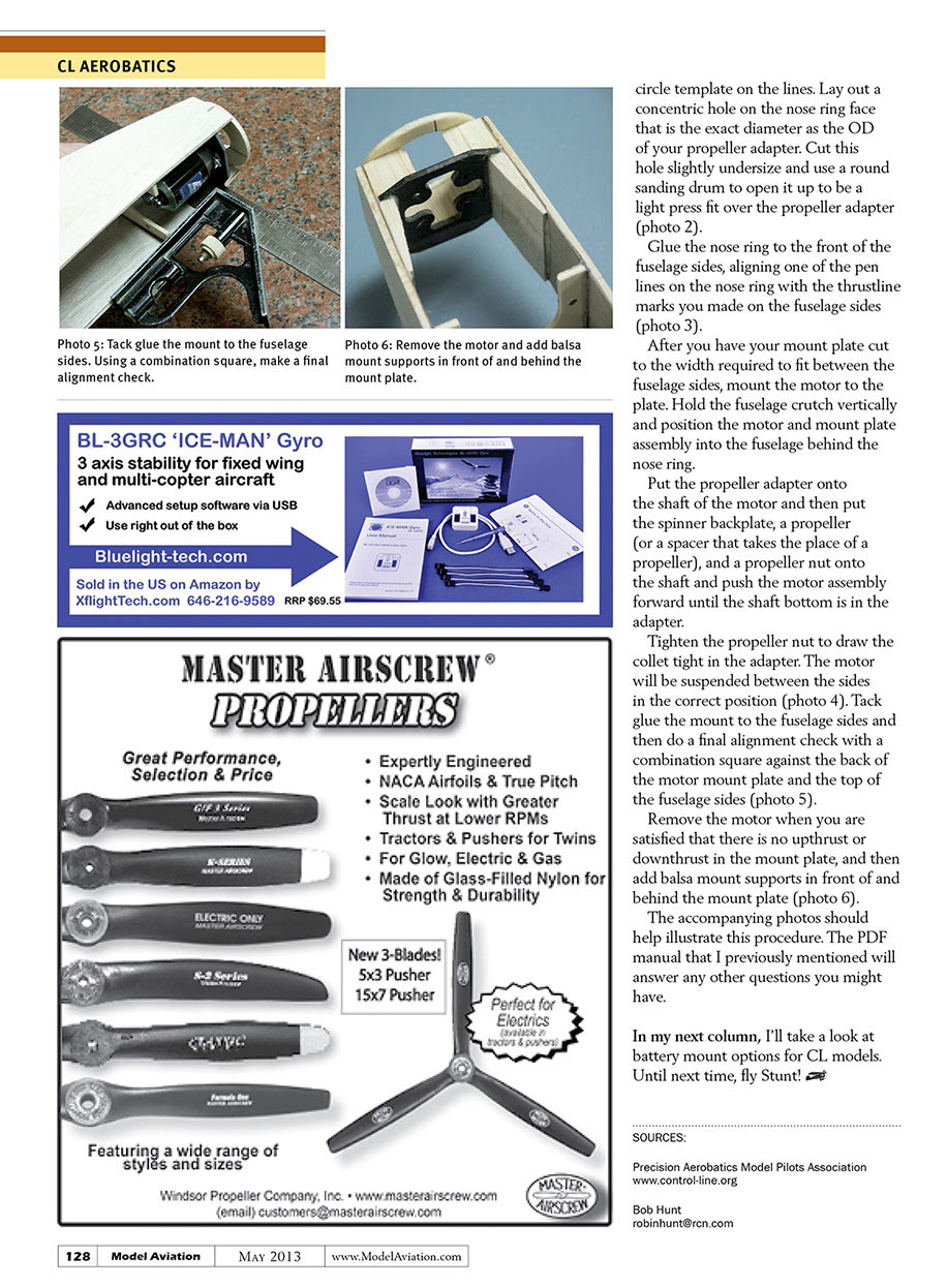
Tighten the propeller nut to draw the collet tight in the adapter. The motor will be suspended between the sides in the correct position (photo 4). Tack glue the mount to the fuselage sides and then do a final alignment check with a combination square against the back of the motor mount plate and the top of the fuselage sides (photo 5).
Remove the motor when you are satisfied that there is no upthrust or downthrust in the mount plate, and then add balsa mount supports in front of and behind the mount plate (photo 6).
The accompanying photos should help illustrate this procedure. The PDF manual that I previously mentioned will answer any other questions you might have.
In my next column, I’ll take a look at battery mount options for CL models. Until next time, fly Stunt!
SOURCES:
Precision Aerobatics Model Pilots Association www.control-line.org
Bob Hunt [email protected]
Transcribed from original scans by AI. Minor OCR errors may remain.

