
Metal Tank Fuel Delivery Systems
by Rich Lopez [email protected]
When the first CL enthusiasts came up with the idea of tying crepe-paper streamers to the back of a model and chasing it around the sky with a similarly equipped model, they used hard, metal fuel tanks. This took place sometime in the early 1950s, long before I had seen a CL model fly.
The engines these early pioneers used worked hard to suck the fuel out of the tank (suction system). If the tank was positioned too high, too low, or too far away, the engine would run inconsistently. They became difficult to start and needle-valve settings could change after the model was in the air.
The venturi openings for an engine running on suction are limited. The opening cannot be so large that it prevents sucking fuel from the tank.
I would have loved to have been there to see the first cut taken on the first streamer-towing model. At that point, pilots must have begun their quest to get better engine runs with more speed, which would help them cut up crepe-paper streamers.
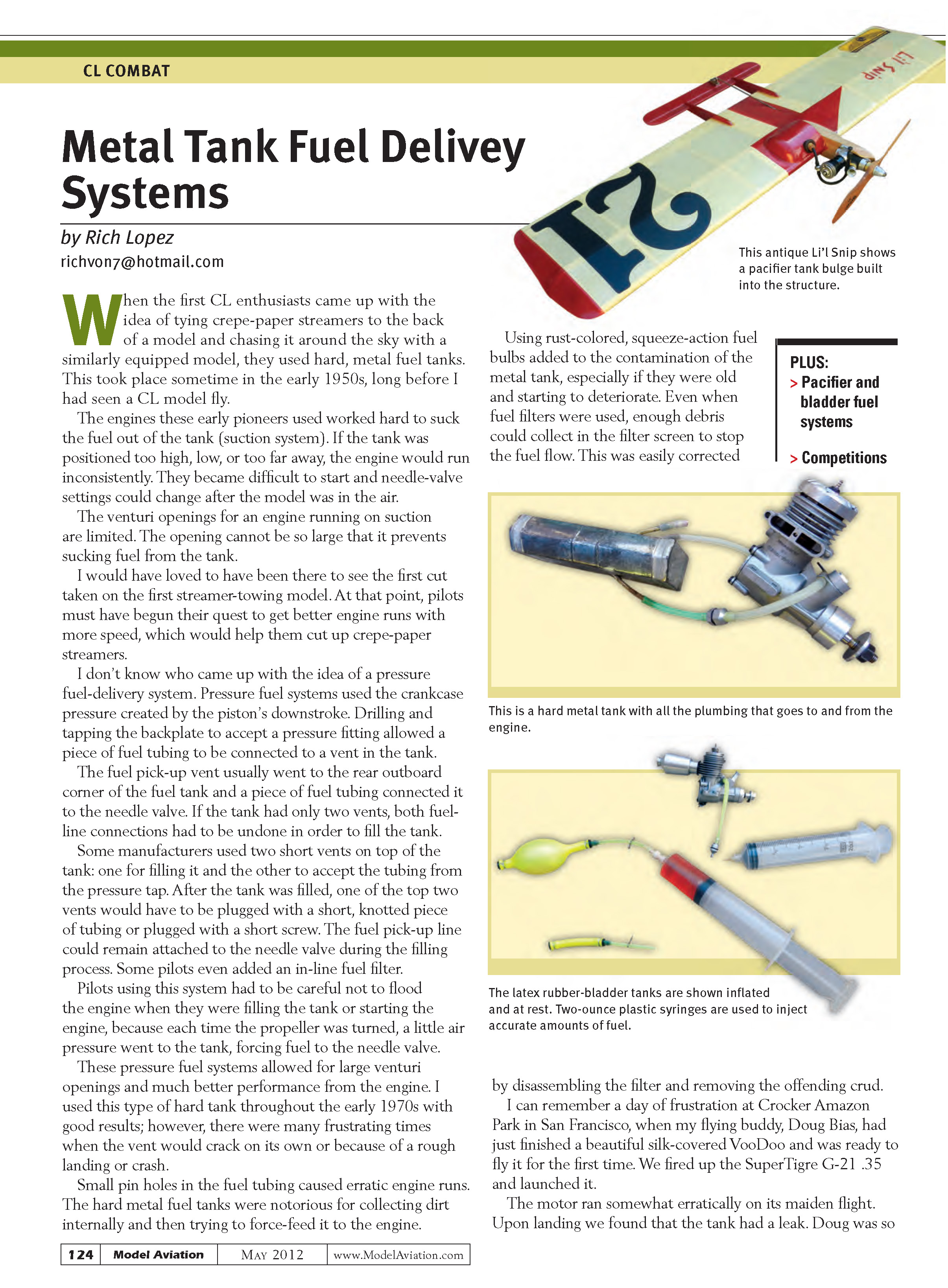
I don’t know who came up with the idea of a pressure fuel-delivery system. Pressure fuel systems used the crankcase pressure created by the piston’s downstroke. Drilling and tapping the backplate to accept a pressure fitting allowed a piece of fuel tubing to be connected to a vent in the tank.
The fuel pick-up vent usually went to the rear outboard corner of the fuel tank and a piece of fuel tubing connected it to the needle valve. If the tank had only two vents, both fuel-line connections had to be undone in order to fill the tank. Some manufacturers used two short vents on top of the tank: one for filling it and the other to accept the tubing from the pressure tap. After the tank was filled, one of the top two vents would have to be plugged with a short, knotted piece of tubing or plugged with a short screw. The fuel pick-up line could remain attached to the needle valve during the filling process. Some pilots even added an in-line fuel filter.
Pilots using this system had to be careful not to flood the engine when they were filling the tank or starting the engine, because each time the propeller was turned, a little air pressure went to the tank, forcing fuel to the needle valve.
These pressure fuel systems allowed for large venturi openings and much better performance from the engine. I used this type of hard tank throughout the early 1970s with good results; however, there were many frustrating times when the vent would crack on its own or because of a rough landing or crash.
Small pinholes in the fuel tubing caused erratic engine runs. The hard metal fuel tanks were notorious for collecting dirt internally and then trying to force-feed it to the engine.
Using rust-colored, squeeze-action fuel bulbs added to the contamination of the metal tank, especially if they were old and starting to deteriorate. Even when fuel filters were used, enough debris could collect in the filter screen to stop the fuel flow. This was easily corrected by disassembling the filter and removing the offending crud.
I can remember a day of frustration at Crocker Amazon Park in San Francisco, when my flying buddy, Doug Bias, had just finished a beautiful silk-covered VooDoo and was ready to fly it for the first time. We fired up the SuperTigre G-21 .35 and launched it.
The motor ran somewhat erratically on its maiden flight. Upon landing we found that the tank had a leak. Doug was so annoyed that he jumped up and down on the painstakingly built VooDoo.
There was a weight penalty to be paid with metal tanks, which prompted a search for lightweight alternative fuel-delivery systems.
Pacifier and Bladder Systems
The first person I remember using pacifier fuel tanks was Alex Sinkevitch at a Western Associated Modelers contest in Northern California.
Alex built lightweight Sneeker models that looked as though they were dancing in the sky. The models were modified so that there was a big bulging compartment behind the engine, which would allow the baby pacifier to expand.
Hollow baby pacifiers could be purchased at almost any drug store. A lead-out eyelet was inserted into a piece of fuel tubing, which was then inserted into the baby pacifier. The pacifier was wrapped at the neck with copper wire or a small rubber band. The unit weighed little, lowering the model's overall weight.
In those days, some pilots still used the same rust-colored fuel bulbs to inflate the baby pacifier with fuel. This often resulted in the fuel bulbs coming apart. It was not an accurate way of knowing how much fuel you had put in the pacifier.
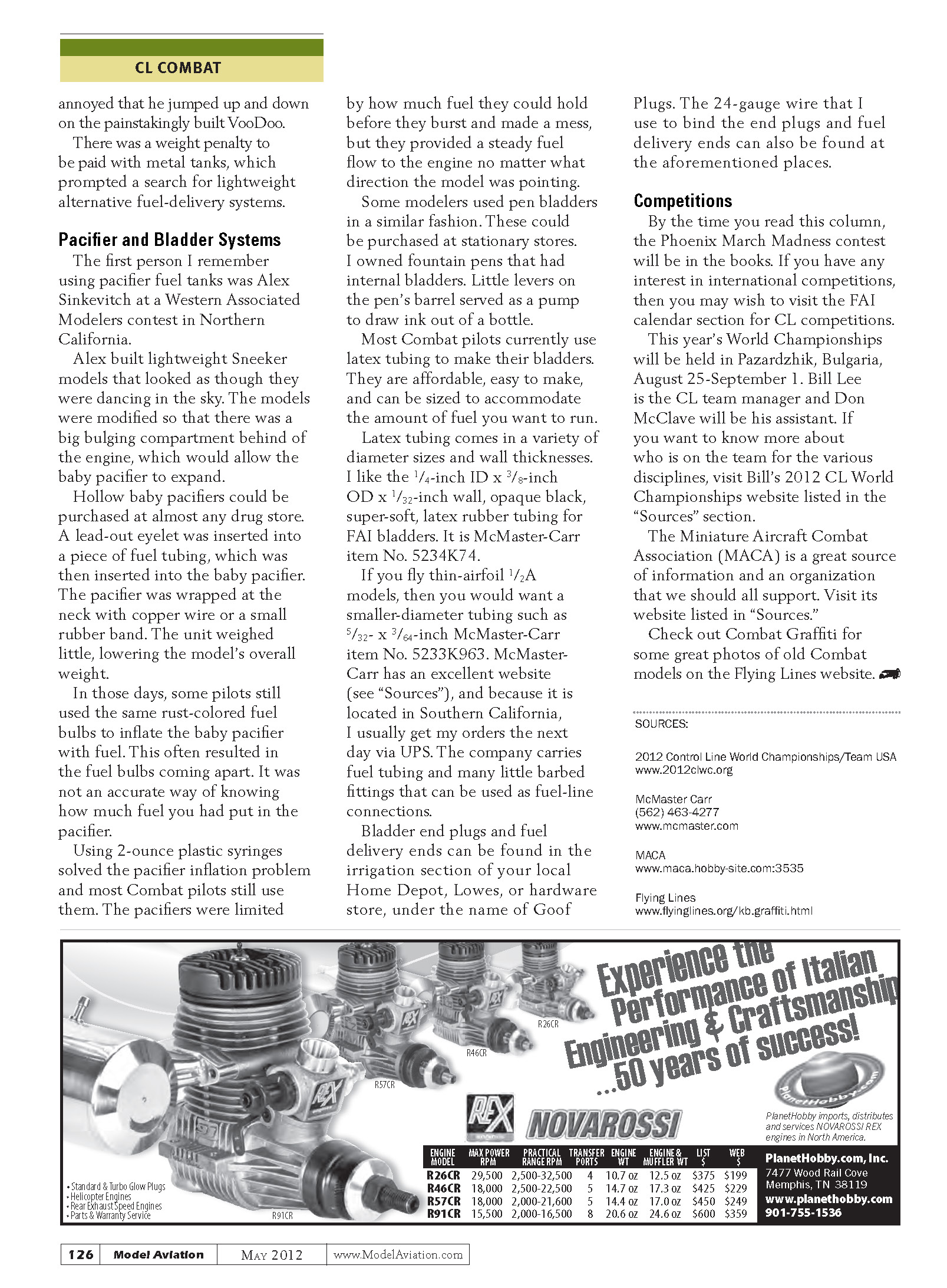
Using 2-ounce plastic syringes solved the pacifier inflation problem and most Combat pilots still use them. The pacifiers were limited by how much fuel they could hold before they burst and made a mess, but they provided a steady fuel flow to the engine no matter what direction the model was pointing.
Some modelers used pen bladders in a similar fashion. These could be purchased at stationery stores. I owned fountain pens that had internal bladders. Little levers on the pen's barrel served as a pump to draw ink out of a bottle.
Most Combat pilots currently use latex tubing to make their bladders. They are affordable, easy to make, and can be sized to accommodate the amount of fuel you want to run.
Latex tubing comes in a variety of diameter sizes and wall thicknesses. I like the 1/4-inch ID x 3/8-inch OD x 1/32-inch wall, opaque black, super-soft, latex rubber tubing for FAI bladders. It is McMaster-Carr item No. 5234K74.
If you fly thin-airfoil 1/2A models, then you would want a smaller-diameter tubing such as 5/32 x 3/64-inch, McMaster-Carr item No. 5233K963. McMaster-Carr has an excellent website (see "Sources"), and because it is located in Southern California, I usually get my orders the next day via UPS. The company carries fuel tubing and many little barbed fittings that can be used as fuel-line connections.
Bladder end plugs and fuel delivery ends can be found in the irrigation section of your local Home Depot, Lowe’s, or hardware store, under the name of Goof Plugs. The 24-gauge wire that I use to bind the end plugs and fuel delivery ends can also be found at the aforementioned places.
Competitions
By the time you read this column, the Phoenix March Madness contest will be in the books. If you have any interest in international competitions, then you may wish to visit the FAI calendar section for CL competitions.
This year's World Championships will be held in Pazardzhik, Bulgaria, August 25–September 1. Bill Lee is the CL team manager and Don McClave will be his assistant. If you want to know more about who is on the team for the various disciplines, visit Bill's 2012 CL World Championships website listed in the "Sources" section.
The Miniature Aircraft Combat Association (MACA) is a great source of information and an organization that we should all support. Visit its website listed in "Sources."
Check out Combat Graffiti for some great photos of old Combat models on the Flying Lines website.
Transcribed from original scans by AI. Minor OCR errors may remain.

