
Stamping the passport for the World Championships
Rich Lopez
EVEN-NUMBERED YEARS are eventful, because that is when World Championships are held. Although there are also plenty of competitions across the country and just across the border in Canada, the World Championships holds a special status.
As I write this column, it is just days before the team of Richard Stubblefield, Michael "Emo" Willcox, and Andy Mears hop on their flight bound for a historic area in the Alsace Lorraine region of France, to compete in the F2D (FAI CL Combat) World Championships.
France and Germany have been fighting over this area for centuries. The famous Maginot Line of defenses is just a few kilometers from where .15-size powered models will be stressed and tested in aerial battles. However, these Combat battles are not accompanied by the high cost they were when French Nieuports did battle with German Fokkers during World War I.
Before the World Championships teams began arriving, the French organizers hosted the Grand Prix of France World Cup. Roy Krupa, Allen Devueve, Mark Rudner, Tom Seigler, Lester Haury, and I joined Emo Willcox and Richard Stubblefield in doing battle with some other countries' official team members, their pit crews, and other pilots who did not make it onto the national teams. I will give you a full and detailed report on our experience in my January 2009 column.
In that column I also intend to carefully examine and photograph any newly developed shutoff devices. Several people around the globe are working on small electronic devices. I am not fluent in electric/technospeak; however, I do have an eye for compact and efficient products. January will be here before we can catch our breath and rapidly say "shutoff required" three times.
Howard Rush, the assistant team manager for Team USA and a semiretired Boeing engineer, is developing electronic gadgets with Preston Briggs. I am curious to see what they come up with.
Howard has built a reputation for thinking out of the box. An example of that is his FAI Snort design that he used in the same region of France in 1990, when he was a member of the US Combat team.
I like to carefully examine engines and the evolution of a particular design. Sometimes the changes are subtle and other times they are complete redesigns. The slight changes are sometimes difficult to detect with the naked eye and require the use of calipers and micrometers.
F2D engine builders seek to produce units that will reliably deliver maximum power with low weight. They will start out with a particular design and then, through tests, modify the product to make it stronger, lighter, or more powerful.
I am curious to know why some manufacturers added a threaded ring to the front bearing housing on the case. I know that the reverse threaded ring holds the front bearing in place, but I also know that the press fit that other engine builders use works fine. I wonder if there was a significant number of bearing failures that caused the manufacturers to build in this function.
The accepted and most common way to extract the front bearing is to disassemble the engine to the case and bearings. Use a propane torch to heat the case around the bearing housing, making sure that you firmly hold the case by the mounting lugs with a pair of pliers.
Once the engine case is heated, you can gently tap out the front bearing from within the case using a nut driver that fits through the crankshaft channel. You can also use a wooden dowel to tap out the bearing.
To fit a new bearing, I put it on the crankshaft so I have something that will align and guide the bearing into its correct position in the case. The crankshaft, with bearing in place, will be guided into a reheated crankcase from the front of the engine.
You could use a vise to hold the engine during this operation; just make certain that the vise clamps down on the engine’s lugs and not its body. I like to let the engine cool before I remove the crankshaft from the newly installed front bearing.
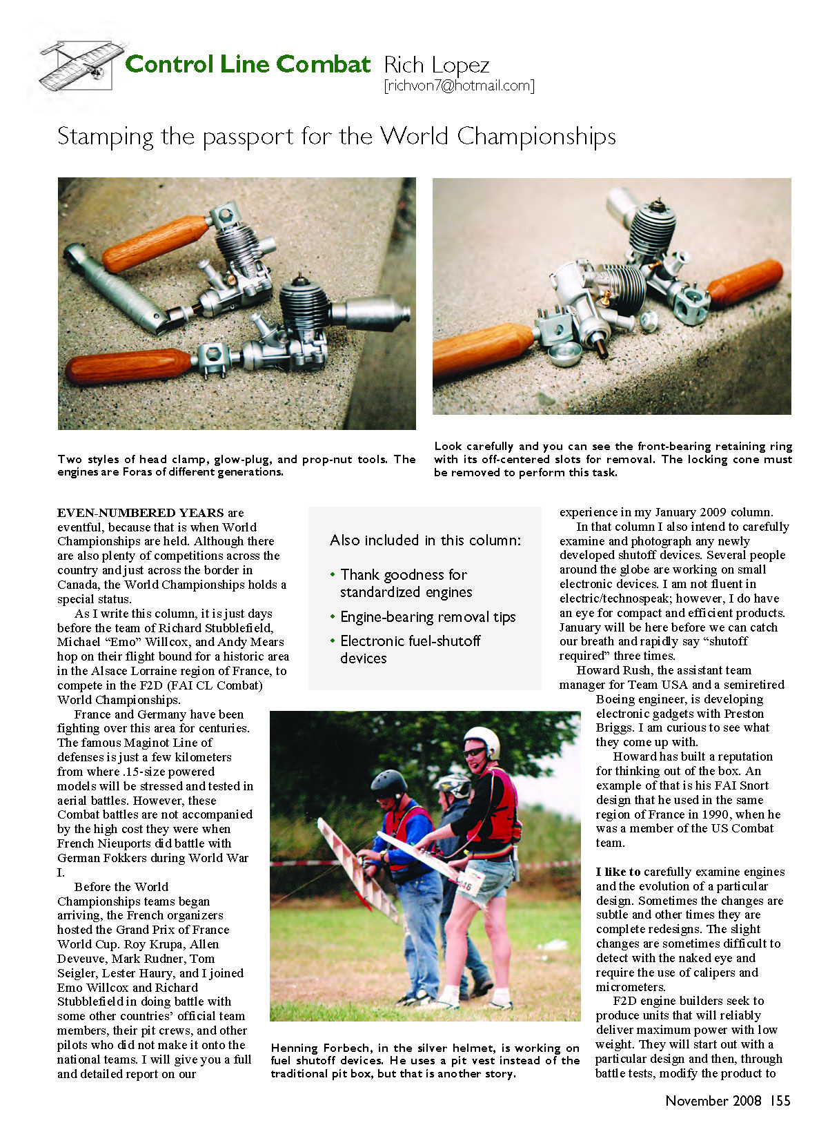
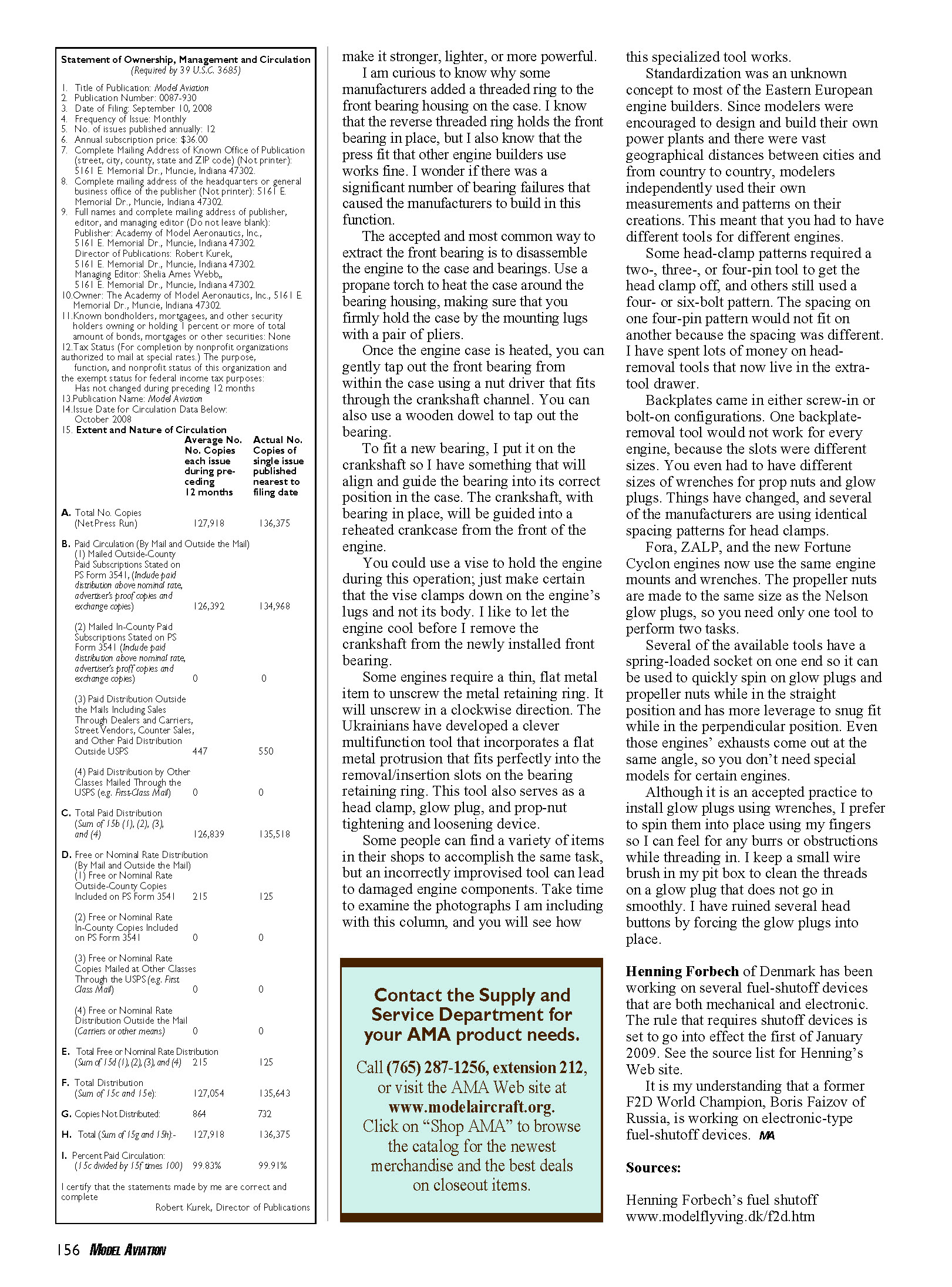
Some engines require a thin, flat metal item to unscrew the metal retaining ring. It will unscrew in a clockwise direction. The Ukrainians have developed a clever multifunction tool that incorporates a flat metal protrusion that fits perfectly into the removal/insertion slots on the bearing retaining ring. This tool also serves as a head clamp, glow plug, and prop-nut tightening and loosening device.
Some people can find a variety of items in their shops to accomplish the same task, but an incorrectly improvised tool can lead to damaged engine components. Take time to examine the photographs I am including with this column, and you will see how this specialized tool works.
Standardization was an unknown concept to most of the Eastern European engine builders. Since modelers were encouraged to design and build their own power plants and there were vast geographical distances between cities and from country to country, modelers independently used their own measurements and patterns on their creations. This meant that you had to have different tools for different engines.
Some head-clamp patterns required a two-, three-, or four-pin tool to get the head clamp off, and others still used a four- or six-bolt pattern. The spacing on one four-pin pattern would not fit on another because the spacing was different. I have spent lots of money on head-removal tools that now live in the extra-tool drawer.
Backplates came in either screw-in or bolt-on configurations. One backplate-removal tool would not work for every engine, because the slots were different sizes. You even had to have different sizes of wrenches for prop nuts and glow plugs. Things have changed, and several of the manufacturers are using identical spacing patterns for head clamps.
Fora, ZALP, and the new Fortune Cyclon engines now use the same engine mounts and wrenches. The propeller nuts are made to the same size as the Nelson glow plugs, so you need only one tool to perform two tasks.
Several of the available tools have a spring-loaded socket on one end so it can be used to quickly spin on glow plugs and propeller nuts while in the straight position and has more leverage to snug fit while in the perpendicular position. Even those engines’ exhausts come out at the same angle, so you don’t need special models for certain engines.
Although it is an accepted practice to install glow plugs using wrenches, I prefer to spin them into place using my fingers so I can feel for any burrs or obstructions while threading in. I keep a small wire brush in my pit box to clean the threads on a glow plug that does not go in smoothly. I have ruined several head buttons by forcing the glow plugs into place.
Henning Forbech of Denmark has been working on several fuel-shutoff devices that are both mechanical and electronic. The rule that requires shutoff devices is set to go into effect the first of January 2009. See the source list for Henning’s Web site.
It is my understanding that a former F2D World Champion, Boris Faizov of Russia, is working on electronic-type fuel-shutoff devices. MA
Also included in this column:
- Thank goodness for standardized engines
- Engine-bearing removal tips
- Electronic fuel-shutoff devices
Sources:
Henning Forbech’s fuel shutoff www.modelflying.dk/f2d.htm
Transcribed from original scans by AI. Minor OCR errors may remain.

