

CONTROL LINE NAVY CARRIER
Dick Perry, 427 Live Oak Ln. NE, Albuquerque NM 87122; E-mail: [email protected]
MYSTERY AIRPLANE
There was a great response to the Mystery Airplane contest in the February issue. Thanks to all who participated.
Of the many correct responses, Dick Hawes of Omaha, Nebraska was selected at random to receive the year's membership in the Navy Carrier Society. Congratulations, Dick.
This month it's back to three-views for the contest.
Because it's been a while since I've had a reasonably conventional single-engine aircraft as the Mystery Airplane, I thought I'd give you an aircraft that should warm the hearts of Guardian-lovers everywhere.
All right—I lied; it's not really a conventional single-engine aircraft, though it is as much a single-engine aircraft as the prototype Guardian was.
This aircraft has a very nice high-aspect-ratio wing, as does the Guardian, and it has a relatively small fuselage—another characteristic that made the Guardian popular. The turboprop engine and spinner would make it even sleeker than the Guardian.
When you think you've identified the aircraft, drop me a line or E-mail me at the address shown in the column header. Good luck.
WINTER PROJECTS
I heard from Bill Calkins about his winter project (it's February as I write this); he completed a beautiful Fairey Firefly for Class I.
With a 42-inch span, the airplane has a wing area of roughly 340 square inches. Bill's model is one of the later variants of the Firefly, with the clipped wingtips and the radiators in the wing roots. It weighs in at 54 ounces, with an O.S. VRP for power, and a pressure fuel system.
I hope to have a photo to show you next time.
John Vina has been working on an XFY-1, which should be really interesting. I drew the outlines for one a long time ago, but I didn't have the courage to start construction. I'm glad that John did, and I'm looking forward to seeing it.
As I mentioned in the April column, I'd really like to publish photos of your latest creations.
Since I won't be able to attend the Nationals this year, photos of your projects are even more important to me because I won't be able to photograph them myself.
I have received a couple of great pictures by E-mail, but Model Aviation requires prints from which to work. Conventional glossy prints—preferably in 4 x 6-inch format or larger—are best.
If you've made the transition to digital photography and can generate a high-resolution print on photo-quality paper, I'll be happy to give that a try.
Since I haven't received any photos from you yet, I'm reduced to publishing my own models.
MODELS AND MODIFICATIONS
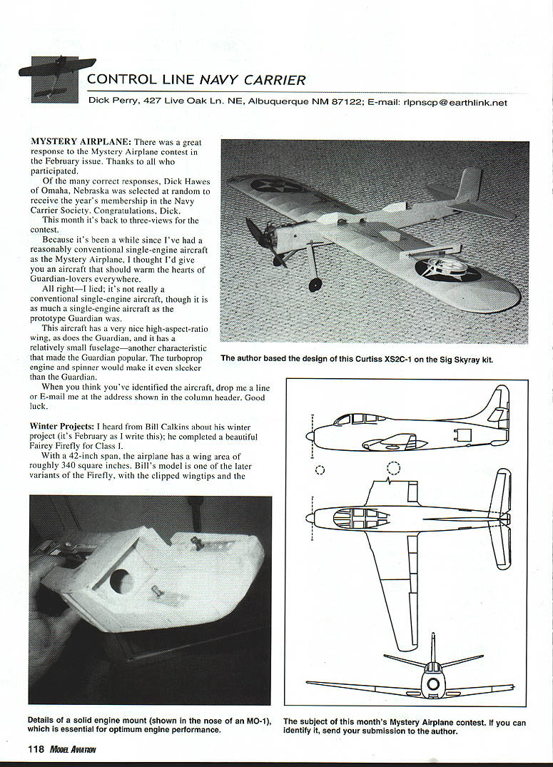
In one photo is a Curtiss XS2C-1. The full-scale aircraft didn't make it with the Navy in an age of biplanes; it was ungainly on a carrier deck. With its wire-braced wings, it was much like the wire-braced biplanes of the day—its wings didn't fold. Unfortunately, its 44-foot span was about 10 feet larger than the contemporary biplanes.
The XS2C-1 model is based on Sig's Skyray 35 kit. The fuselage outline is modified with a couple small pieces of 1/2-inch stock, and a few minor cuts to produce the proper outlines for the XS2C. New tail feathers and wingtips complete the conversion.
The XS2C-1 hasn't been flown much yet. It is nose-heavy—even with a relatively light Fox MK IV in the nose—and I haven't achieved proper flight trim for high speed yet. I doubt that the XS2C-1 will ever achieve really great high speed, because the design suffers from a common fault in Profile-class models of similar configuration: the nose is too long to provide a solid mount for the engine. The Fox shakes too much on the flexible nose.
I didn't go beyond the materials in the kit when I designed the model. It would have benefitted from additional reinforcement on the inboard side (up to the allowable 1½-inch total thickness). Fiberglass, or even carbon, on the surface would have helped too. An engine can reach its maximum potential with a proper mount to control vibration. A flexible mount will keep the engine from performing up to the level you would see on a solid mount.
A pressure engine with an appropriately sized venturi should pull today's large Carrier models faster than 100 mph. My stock O.S. .40 VF (out of the box, standard carburetor, no rework) will go more than 90 mph on suction on my 340-square-inch, 49-ounce MO-1.
ENGINE MOUNTING AND NOSE STRUCTURE
Another photo shows the structure in the nose of my MO-1 designs.
- The engine mounts are 1/2" square maple with 1/8" birch plywood, for a total thickness of 3/4".
- The mounts are tied solidly to the 1/32" plywood fuselage sides.
- The inboard four fuselage side extensions to the nose have solid balsa fill between the plywood and the engine mounts.
- Two 3/32" birch plywood triangles on the front and 1/2" triangular balsa fillets on the back of the firewall ensure a solid connection to the outboard fuselage side. A plywood firewall alone is not stiff enough.
- The engine is mounted on aluminum pads, which are epoxied to the engine mounts. The aluminum distributes the load from the engine lugs throughout a larger area than if the lugs themselves contacted the wood.
- The aluminum pads are milled flat, so there is no distortion of the engine lugs or case, which could increase internal stress on the bearings. The milling is the last step after the model has been painted, so I know the mounts will stay flat.
It may sound obsessive, but it works.
NOTES AND FINDS
Ted Kraver has been sending me some interesting articles in the past months. Ted was the first editor of the Hi-Low Landings newsletter, and one of the forces in establishing the Navy Carrier Society back before the Riverside, California Nationals.
Ted loves finding obscure Carrier aircraft as much as I do. A couple of his finds will be featured in future Mystery Airplane contests, so I won't give those away.
One beautiful aircraft from Lockheed that didn't make it off the drawing board was the L-178-1. A patrol bomber concept with a turboprop in the nose and two jets in the tail, it sported a V-tail and an elliptical wing. It's a shame the aircraft wasn't built.
The L-178's predecessor in the Lockheed design sequence was the L-177, which was to be a version of the P-80 Shooting Star for the Navy.
Although the P-80 design didn't make it either, the Navy used three P-80As after they started service in the Army Air Corps. One of the aircraft was fitted with arresting hook and catapult gear, and was tested aboard the USS Franklin D. Roosevelt.
Though the L-178 would be legal for our event, building one would be a real challenge.
A while ago, I provided a URL (Universal Resource Locator, or address) for the Smithsonian's Web site, which had images of C-130 Carrier trials. Unfortunately the URL in that particular issue never did fly straight after those tests.
I was scratching my head, trying to think of other four-engine aircraft that might have had at least one trial on a carrier, or that could have been designed for the purpose, but I couldn't come up with any candidates.
I had forgotten my college days, when I worked for a short period at the XC-142A System Program Office at Wright-Patterson Air Force Base. Although the trials occurred after I left the office, the four-engined XC-142A did land and take off from a carrier deck during its flight-test program. The aircraft was built as a tri-service aircraft, so the Navy wanted to demonstrate it on a carrier.
As with the C-130, the XC-142A didn't use arresting gear; it could take off and land vertically because of the tilt-wing configuration, making arresting gear superfluous.
The Air and Space Museum has added a page to its Web site for aircraft "Too Ugly to Print." You can find it at www.airspacemag.com/ASM/Mag/Supp/1997/ugly.html.
While you're there, look up the presentation on George Aldrich's No. 8 True; it's a stunt model, but one of the photos is of George's model in US Navy colors.
MA
Transcribed from original scans by AI. Minor OCR errors may remain.

