
Introduction
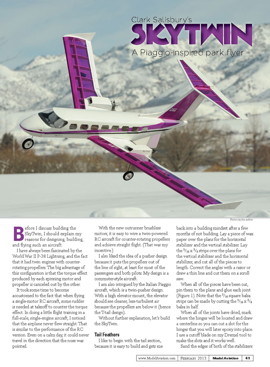
Before I discuss building the SkyTwin, I should explain my reasons for designing, building, and flying such an aircraft.
I have always been fascinated by the World War II P-38 Lightning and its twin engines with counter-rotating propellers. The big advantage of this configuration is that the torque effect produced by each spinning motor and propeller is canceled out by the other.
It took some time to become accustomed to the fact that when flying a single-motor RC aircraft, some rudder is needed at takeoff to counter the torque effect. In doing a little flight training in a full-scale, single-engine aircraft, I noticed that the airplane never flew straight. That is similar to the performance of the RC version. Even on a calm day, it could never travel exactly in the direction that the nose was pointed.
With the new outrunner brushless motors, it is easy to wire a twin-powered RC aircraft for counter-rotating propellers and achieve straight flight. That was my incentive.
I also liked the idea of a pusher design because it puts the propellers out of the line of sight, at least for most of the passengers and both pilots. My design is a commuter-style aircraft.
I am also intrigued by the Italian Piaggio aircraft, which is a twin-pusher design. With a high elevator mount, the elevator should see cleaner, less-turbulent air because the propellers are below it (hence the T-tail design).
Without further explanation, let's build the SkyTwin.
Tail Feathers
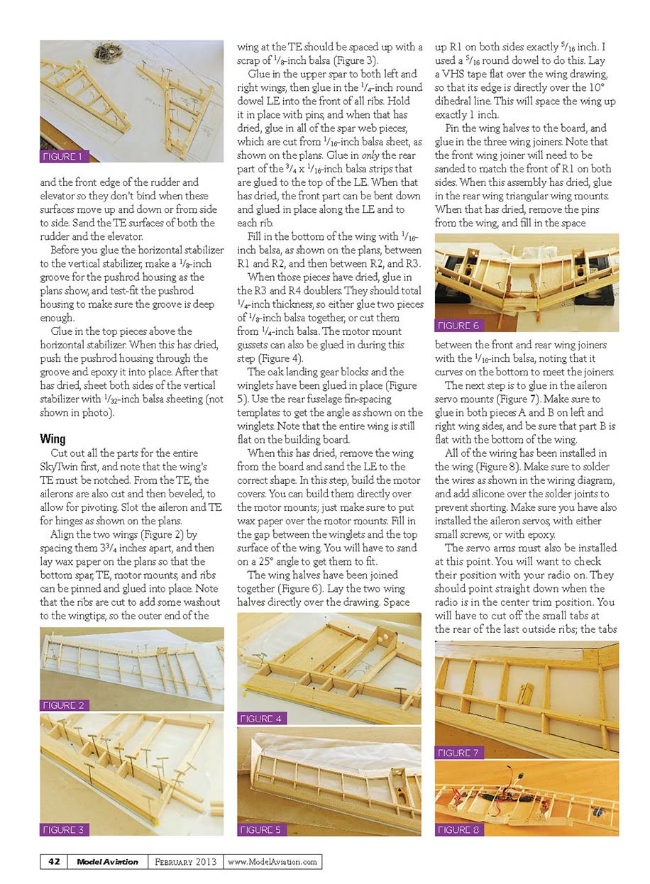
Lay a piece of wax paper over the plans for the horizontal stabilizer and the vertical stabilizer. Lay the 3/16 x 3/8-inch strips over the plans for both stabilizers and cut all of the pieces to length. Correct the angles with a razor or draw a thin line and cut them on a scroll saw. When all pieces have been cut, pin them to the plans and glue each joint (Figure 1). Note that the 3/16-inch square balsa strips can be made by cutting the 3/16 x 3/8-inch balsa in half.
When the joints have dried, mark where the hinges will be located and draw a centerline so you can cut a slot for the hinges that you will later epoxy into place. I use a cutoff blade on my Dremel tool to make the slots and it works well. Sand the edges of both stabilizers and the front edges of the rudder and elevator so they don't bind when these surfaces move up and down or side to side. Sand the trailing-edge (TE) surfaces of both the rudder and the elevator.
Before you glue the horizontal stabilizer to the vertical stabilizer, make a 1/8-inch groove for the pushrod housing as the plans show, and test-fit the pushrod housing to make sure the groove is deep enough. Glue in the top pieces above the horizontal stabilizer. When this has dried, push the pushrod housing through the groove and epoxy it into place. After that has dried, sheet both sides of the vertical stabilizer with 1/32-inch balsa sheeting (not shown in photo).
Wing
Cut out all the parts for the entire SkyTwin first. Note that the wing's TE must be notched. From the TE, cut out the ailerons and bevel them to allow for pivoting. Slot the aileron and TE for hinges as shown on the plans.
Align the two wings by spacing them 3 3/4 inches apart, then lay wax paper on the plans so the bottom spar, TE, motor mounts, and ribs can be pinned and glued into place (Figure 2). The ribs are cut to add some washout to the wingtips, so the outer end of the wing at the TE should be spaced up with a scrap of 1/8-inch balsa (Figure 3).
Glue in the upper spar to both left and right wings, then glue in the 1/4-inch round dowel leading edge (LE) into the front of all ribs. Hold it in place with pins. When that has dried, glue in all of the spar web pieces, which are cut from 1/16-inch balsa sheet, as shown on the plans. Glue in only the rear part of the 3/4 x 1/16-inch balsa strips that are glued to the top of the LE. When that has dried, the front part can be bent down and glued in place along the LE and to each rib.
Fill in the bottom of the wing with 1/16-inch balsa, as shown on the plans, between R1 and R2, and then between R2 and R3.
When those pieces have dried, glue in the R3 and R4 doublers. They should total 1/4-inch thickness, so either glue two pieces of 1/8-inch balsa together or cut them from 1/4-inch balsa. The motor mount gussets can also be glued in during this step (Figure 4).
Glue the oak landing gear blocks and the winglets in place (Figure 5). Use the rear fuselage fin-spacing templates to get the angle as shown on the winglets. Note that the entire wing is still flat on the building board.
When this has dried, remove the wing from the board and sand the LE to the correct shape. In this step, build the motor covers. You can build them directly over the motor mounts; just make sure to put wax paper over the motor mounts. Fill in the gap between the winglets and the top surface of the wing. You will have to sand on a 25° angle to get them to fit.
Join the wing halves together (Figure 6). Lay the two wing halves directly over the drawing. Space up R1 on both sides exactly 1/16 inch (I used a 5/16-inch round dowel to do this). Lay a VHS tape flat over the wing drawing so that its edge is directly over the 10° dihedral line; this will space the wing up exactly 1 inch.
Pin the wing halves to the board and glue in the three wing joiners. Note that the front wing joiner will need to be sanded to match the front of R1 on both sides. When this assembly has dried, glue in the rear triangular wing mounts. When that has dried, remove the pins from the wing and fill in the space between the front and rear wing joiners with 1/16-inch balsa, noting that it curves on the bottom to meet the joiners.
Next, glue in the aileron servo mounts (Figure 7). Make sure to glue in both pieces A and B on left and right wing sides, and be sure that part B is flat with the bottom of the wing.
Install the wiring in the wing (Figure 8). Make sure to solder the wires as shown in the wiring diagram, and add silicone over the solder joints to prevent shorting. Install the aileron servos with either small screws or epoxy.
Install the servo arms and check their position with your radio on. They should point straight down when the radio is in the center trim position. You will have to cut off the small tabs at the rear of the last outside ribs; the tabs hold in washout.
Now the wing can be covered. Be careful not to introduce any twist into the wing; it has built-in washout.
Fuselage
Begin with the nose piece. Cut the balsa block as shown on the plans so the profile matches all three views. Glue the two balsa blocks together. Cut out the balsa to create the cooling hole in the center and the 1/4-inch diameter holes for the mounting on both sides. Although not shown on the drawing, notch the bottom part so the nose gear doesn't interfere when the landing gear is installed on the front of F1.
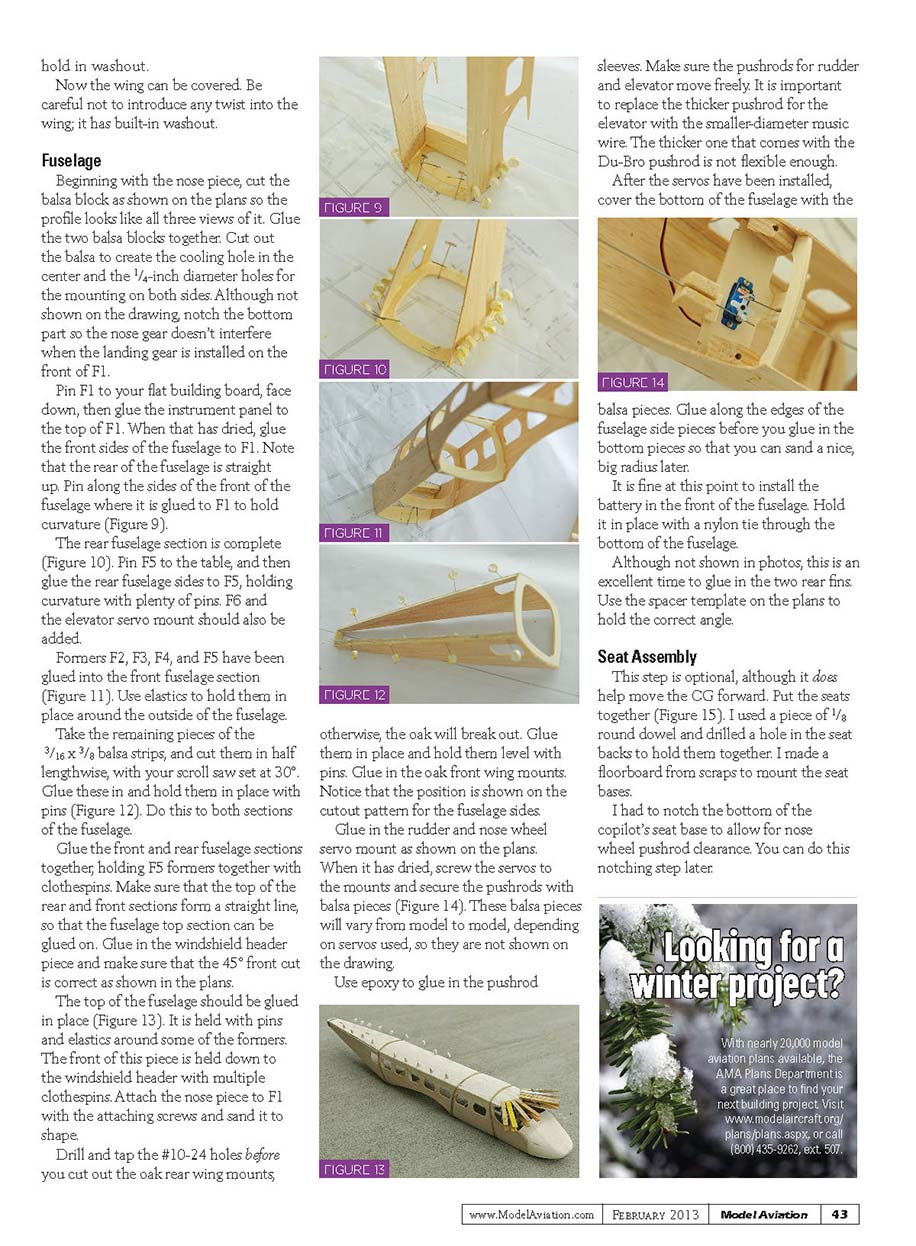
Pin F1 to your flat building board, face down, then glue the instrument panel to the top of F1. When that has dried, glue the front sides of the fuselage to F1. Note that the rear of the fuselage is straight up. Pin along the sides of the front of the fuselage where it is glued to F1 to hold curvature (Figure 9).
Pin F5 to the table, and then glue the rear fuselage sides to F5, holding curvature with plenty of pins (Figure 10). Add F6 and the elevator servo mount.
Formers F2, F3, F4, and F5 have been glued into the front fuselage section (Figure 11). Use elastics to hold them in place around the outside of the fuselage.
Take the remaining pieces of the 3/16 x 3/8-inch balsa strips and cut them in half lengthwise with your scroll saw set at 30°. Glue these in and hold them in place with pins (Figure 12). Do this to both sections of the fuselage.
Glue the front and rear fuselage sections together, holding F5 formers together with clothespins. Make sure that the top of the rear and front sections form a straight line so the fuselage top section can be glued on. Glue in the windshield header piece and make sure that the 45-degree front cut is correct as shown in the plans.
Glue the top of the fuselage in place (Figure 13). It is held with pins and elastics around some of the formers. The front of this piece is held down to the windshield header with multiple clothespins. Attach the nose piece to F1 with the attaching screws and sand it to shape.
Drill and tap the #10-24 holes before you cut out the oak rear wing mounts; otherwise, the oak will break out. Glue them in place and hold them level with pins. Glue in the oak front wing mounts. The positions are shown on the cutout pattern for the fuselage sides.
Glue in the rudder and nose-wheel servo mounts as shown on the plans. When they have dried, screw the servos to the mounts and secure the pushrods with balsa pieces (Figure 14). These balsa pieces will vary from model to model, depending on the servos used, so they are not shown on the drawing.
Use epoxy to glue in the pushrod sleeves. Make sure the pushrods for rudder and elevator move freely. It is important to replace the thicker pushrod for the elevator with smaller-diameter music wire; the thicker one that comes with the Du-Bro pushrod is not flexible enough.
After the servos have been installed, cover the bottom of the fuselage with the balsa pieces. Glue along the edges of the fuselage side pieces before you glue in the bottom pieces so that you can sand a nice, big radius later.
It is fine at this point to install the battery in the front of the fuselage. Hold it in place with a nylon tie through the bottom of the fuselage.
Although not shown in photos, this is an excellent time to glue in the two rear fins. Use the spacer template on the plans to hold the correct angle.
Seat Assembly
This step is optional, although it does help move the center of gravity forward.
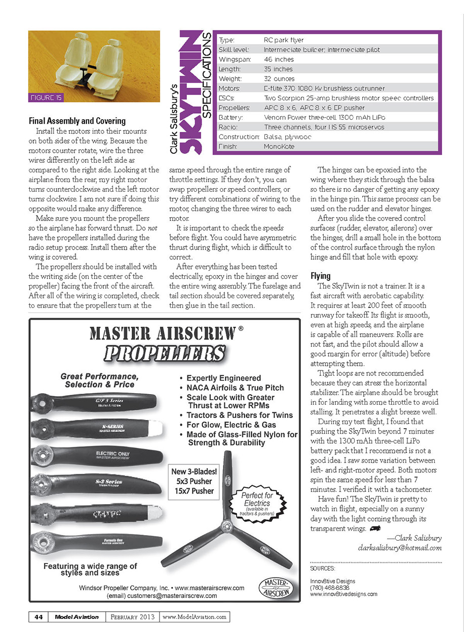
Put the seats together (Figure 15). I used a piece of 1/8-inch round dowel and drilled a hole in the seat backs to hold them together. I made a floorboard from scraps to mount the seat bases.
I had to notch the bottom of the copilot's seat base to allow for nose-wheel pushrod clearance. You can do this notching step later if preferred.
Final Assembly and Covering
Install the motors into their mounts on both sides of the wing. Because the motors counter-rotate, wire the three wires differently on the left side compared to the right side. Looking at the airplane from the rear, my right motor turns counterclockwise and the left motor turns clockwise. I am not sure if doing this opposite would make any difference.
Make sure you mount the propellers so the airplane has forward thrust. Do not have the propellers installed during the radio setup process. Install them after the wing is covered.
The propellers should be installed with the writing side (on the center of the propeller) facing the front of the aircraft. After all of the wiring is completed, check to ensure that the propellers turn at the same speed through the entire range of throttle settings. If they don't, you can swap propellers or speed controllers, or try different combinations of wiring to the motor, changing the three wires to each motor.
It is important to check the speeds before flight. You could have asymmetric thrust during flight, which is difficult to correct.
After everything has been tested electrically, epoxy in the hinges and cover the entire wing assembly. The fuselage and tail section should be covered separately, then glue in the tail section.
The hinges can be epoxied into the wing where they stick through the balsa so there is no danger of getting any epoxy in the hinge pin. This same process can be used on the rudder and elevator hinges.
After you slide the covered control surfaces (rudder, elevator, ailerons) over the hinges, drill a small hole in the bottom of the control surface through the nylon hinge and fill that hole with epoxy.
SKYTWIN SPECIFICATIONS
- Type: RC park flyer
- Skill level: Intermediate builder; intermediate pilot
- Wingspan: 46 inches
- Length: 35 inches
- Weight: 32 ounces
- Motors: E-flite 370, 1080 Kv brushless outrunner (two)
- ESCs: Two Scorpion 25-amp brushless motor speed controllers
- Propellers: APC 8 x 6, APC 8 x 6 E pusher
- Battery: Venom Power 3-cell (11.1V) 1300 mAh LiPo
- Radio: Three channels; four HS-55 microservos
- Construction: Balsa, plywood
- Finish: MonoKote
Flying
The SkyTwin is not a trainer. It is a fast aircraft with aerobatic capability. It requires at least 200 feet of smooth runway for takeoff. Its flight is smooth, even at high speeds, and the airplane is capable of all maneuvers. Rolls are not fast, and the pilot should allow a good margin for error (altitude) before attempting them.
Tight loops are not recommended because they can stress the horizontal stabilizer. The airplane should be brought in for landing with some throttle to avoid stalling. It penetrates a slight breeze well.
During my test flight, I found that pushing the SkyTwin beyond 7 minutes with the 1300 mAh 3-cell LiPo battery pack that I recommend is not a good idea. I saw some variation between left- and right-motor speed. Both motors spin the same speed for less than 7 minutes. I verified it with a tachometer.
Have fun! The SkyTwin is pretty to watch in flight, especially on a sunny day with the light coming through its transparent wings.
-- Clark Salisbury [email protected]
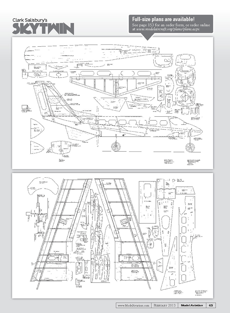
Clark Salisbury's SKYTWIN
Full-size plans are available! See page 153 for an order form, or order online at www.modelaircraft.org/plans/plans.aspx
Sources
- Innov8tive Designs
(760) 468-8838 www.innov8tivedesigns.com
Transcribed from original scans by AI. Minor OCR errors may remain.

