
CLEAN CUT
by Dick Sarpolus
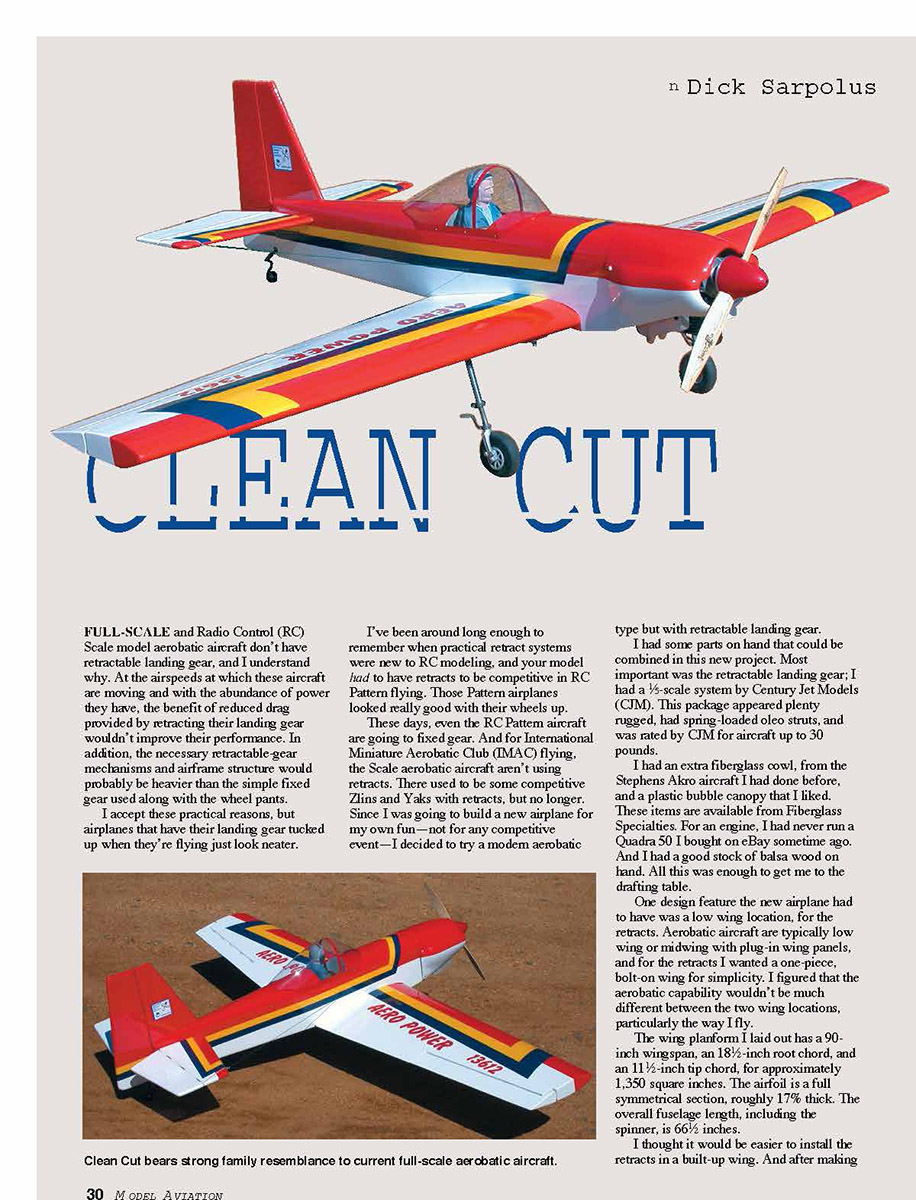
FULL-SCALE and Radio Control (RC) Scale model aerobatic aircraft don't have retractable landing gear, and I understand why. At the airspeeds at which these aircraft are moving and with the abundance of power they have, the benefit of reduced drag provided by retracting their landing gear wouldn't improve their performance. In addition, the necessary retractable-gear mechanisms and airframe structure would probably be heavier than the simple fixed gear used along with the wheel pants.
I accept these practical reasons, but airplanes that have their landing gear tucked up when they're flying just look neater.
I've been around long enough to remember when practical retract systems were new to RC modeling, and your model had to have retracts to be competitive in RC Pattern flight. Those Pattern airplanes looked really good with their wheels up.
These days, even the RC Pattern aircraft are going to fixed gear. And for International Miniature Aerobatic Club (IMAC) flying, the Scale aerobatic aircraft aren't using retracts. There used to be some competitive Zlins and Yaks with retracts, but no longer. Since I was going to build a new airplane for my own fun — not for any competitive event — I decided to try a modern aerobatic type but with retractable landing gear.
I had some parts on hand that could be combined in this new project. Most important was the retractable landing gear; I had a 1/5-scale system by Century Jet Models (CJM). This package appeared plenty rugged, had spring-loaded oleo struts, and was rated by CJM for aircraft up to 30 pounds.
I had an extra fiberglass cowl, from the Stephens Akro aircraft I had done before, and a plastic bubble canopy that I liked. These items are available from Fiberglass Specialties. For an engine, I had never run a Quadra 50 I bought on eBay sometime ago. And I had a good stock of balsa wood on hand. All this was enough to get me to the drawing table.
One design feature the new airplane had to have was a low wing location, for the retracts. Aerobatic aircraft are typically low wing or midwing with plug-in wing panels, and for the retracts I wanted a one-piece, bolt-on wing for simplicity. I figured that the aerobatic capability wouldn't be much different between the two wing locations, particularly the way I fly.
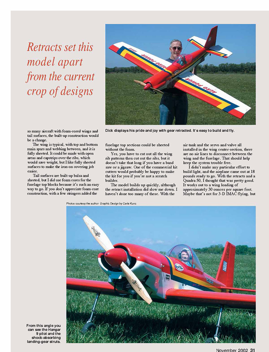
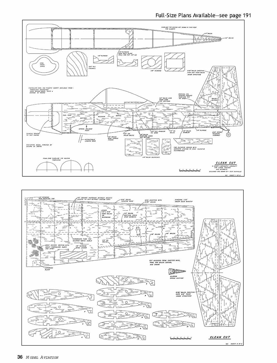
The wing platform I laid out has a 90-inch wingspan, an 18-1/2-inch root chord, and an 11-1/2-inch tip chord, for approximately 1,350 square inches. The airfoil is a fully symmetrical section, roughly 17% thick. The overall fuselage length, including the spinner, is 66-1/2 inches.
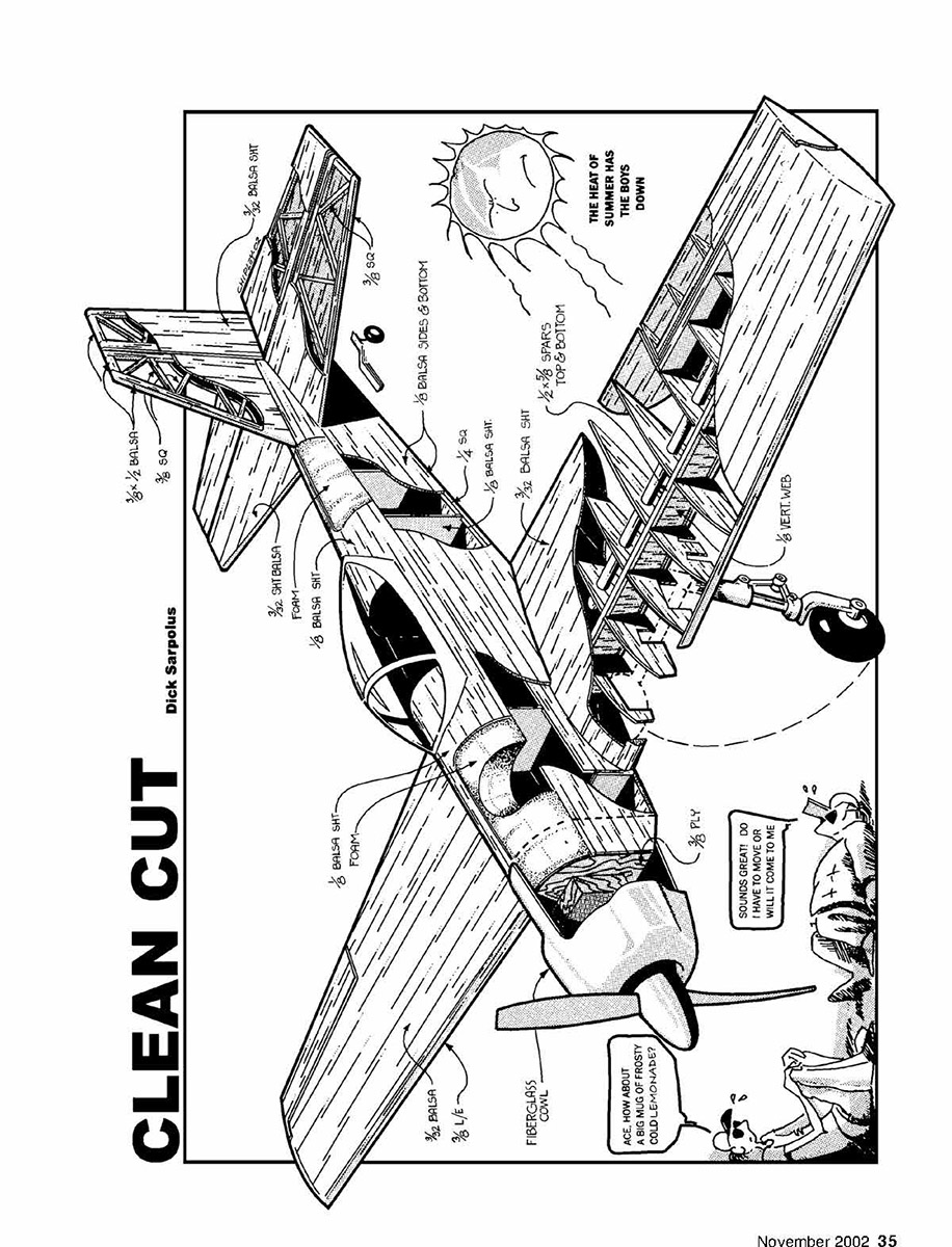
I thought it would be easier to install the retracts in a built-up wing. And after making the wing, I used foam cores for the fuselage top blocks because it's such an easy way to go. If you don't appreciate foam-core construction, with a few stringers added the fuselage top sections could be sheeted without the foam.
Yes, you have to cut out all the wing rib patterns then cut out the ribs, but it doesn't take that long if you have a band saw or a jigsaw. One of the commercial kit cutters would probably be happy to make the kit for you if you're not a scratch builder.
The model builds up quickly, although the retract installation did slow me down. I haven't done too many of these. With the air tank and the servo and valve all installed in the wing center-section, there are no air lines to disconnect between the wing and the fuselage. That should help keep the system trouble free.
I didn't make any particular effort to build light, and the airplane came out at 18 pounds ready to go. With the retracts and a Quadra 50, I thought that was pretty good. It works out to a wing loading of approximately 30 ounces per square foot. Maybe that's not for 3-D IMAC flying, but it's plenty lively for my fun-flying aerobatic stuff—and I like to see those wheels up.
First flights showed that I had just what I wanted: a comfortable-flying airplane with no bad habits that I can relax with, but still enjoy all the aerobatics I want. And it looks great with the wheels pulled up! Those low passes really look good.
A friend remarked that when flying inverted—something I like to do—the wheels weren't sticking up to remind me that the model was upside-down. That's true, but the rudder hanging down gives me a clue.
Using retracts does add something to the flying, such as on the sixth flight when one of the gear legs dropped off as the airplane lifted off the ground. After a good flight I set up for one of those gear-up landings that are always a potential, and on the soft grass field there was no damage to the airplane. The lost-gear-leg problem was solved with a larger setscrew and a notch filed into the strut tube.
CONSTRUCTION
Construction starts with cutting up a set of plans for the part templates. I cut out all the parts before I begin construction, so I had, in effect, a kit. I don't mind working with paper templates of the parts, drawing around them with a ballpoint pen onto the plywood or balsa, and cutting them out with my band saw or jigsaw.
The molded fiberglass cowl and plastic canopy can be ordered from Fiberglass Specialties, 51200 Milano Dr. Suite A, Macomb MI 48042; Tel.: (810) 677-0213. I get all my balsa and plywood mail order and have been happy with the wood from Lone Star Models, 115 Industrial St., Lancaster TX 75134.
I was pleased with the CJM retract landing-gear system, and Robart has a line of retract systems I know would be good. If you like the airplane but don't want to go with retracts, you could use some 1/4-inch-diameter music wire mounted via grooved hardwood blocks in the wing with Robart's RoboStruts, or go with a sheet-aluminum fuselage-mounted gear.
Tail Surfaces
I built the tail surfaces first. There was no particular reason; they're easy and quick to do. I cut the 3/32 balsa sheeting to the surface shape, and with it on the workbench surface I added the inner structure and the top side sheeting, removed it when the glue was dry, and shaped the edges as appropriate.
Fuselage
The fuselage is next. Glue up the sides, adding to the 1/8 balsa side pieces the 1/16 plywood doublers, the 1/8 balsa wing saddle and tail doublers, and the 1/4 square balsa along the lower rear edges.
The plywood firewall and the next three plywood bulkheads are added to one of the fuselage sides at right angles to the side. Then the opposite side is added, and later the tail ends are pulled together and the rear bulkheads are added. Reinforce the firewall installation with triangle stock along the side joints and several small screws through the sides into the firewall.
Fit the foam top blocks to the fuselage structure, sanding them if necessary so that they will fit flush with the sides with the sheeting applied. Sheet the top foam blocks, and glue them to the basic fuselage structure. Don't add the bottom sheeting until the tail pushrods are installed later.
Wing
The first step in the wing construction is to position the lower main spar over the plans. I protect the plans with waxed paper. Only the right wing panel is shown on the plans; to build the left panel, you can position the wing ribs in the opposite direction over the plans or trace a drawing of the spar with the correct rib spacing and use that.
All ribs are located at right angles to the spar, and the "feet" on the ribs will keep them positioned during construction. Add the wing ribs to the lower spar, pinning them to the building surface.
The 1/8 plywood doublers on ribs 4 and 5, which accept the 1/2-inch square hardwood pieces for the retract mounts, should be made and located to suit the particular type of retract system you're using. The retract installation will be completed when the wing panel structure is turned over later. Ribs 2 and 3 are cut out later to clear the retracts and wheels used.
CLEAN CUT
Install the vertical-grain spar webbing between the ribs, then add the upper spar. Also add the 1/4-inch square aileron area spars and the cardboard aileron servo cable tubes. I edge-glued two pieces of 3/32 x 4 x 48-inch balsa and applied it to the top of the wing structure from the leading-edge location back. I made another eight-inch-wide piece of sheeting then added it to the top wing structure.
With the top sheeting in place, the wing panel can be removed from the building board and turned over for finishing. Add the bottom sheeting and trim for the retract installation.
Cut the ailerons from the completed wing, and add 1/8 balsa to face off the aileron opening. Before adding this 1/8 balsa, position balsa blocks between the 1/4-inch rear spars for the hinge installation. Trim back the ailerons, add 1/8 balsa leading edges, and bevel to shape to complete the ailerons.
The extended sections at the aileron and elevator tips are suggested for appearance and/or for adding weight if you feel it appropriate to counterbalance these control surfaces to prevent flutter. I have never had a flutter problem; use strong servos and stiff, strong linkages to aid in preventing it. Some prefer to add counterbalances for insurance.
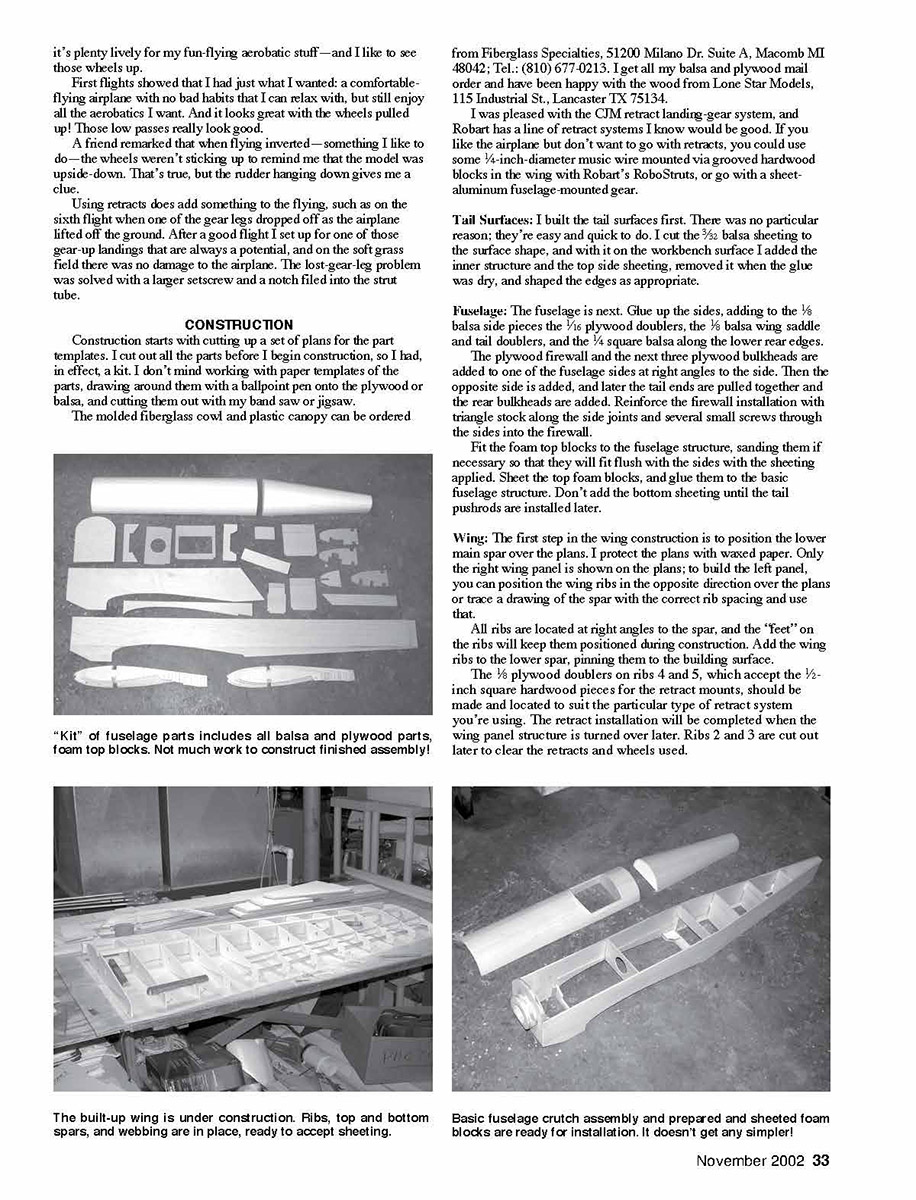
Join the wing panels with a plywood dihedral brace and fiberglass cloth and epoxy reinforcing around the center-section. I cut a hole in the top center-section of the wing for the retract-system air tank and the retract servo, which is linked to the retract control valve.
Final Assembly: Set up the fuselage/wing mounting by adjusting the fit of the plywood tongue in the wing center-section to the fuselage bulkhead that retains the wing. Drill through hardwood blocks installed in the wing trailing edge into the plywood wing-mounting plate in the fuselage, and tap that plate for the two 1/4-20 nylon mounting bolts.
With the wing in place on the fuselage, glue the horizontal stabilizer to the fuselage, lining it up in relation to the wing. Glue the fin in place.
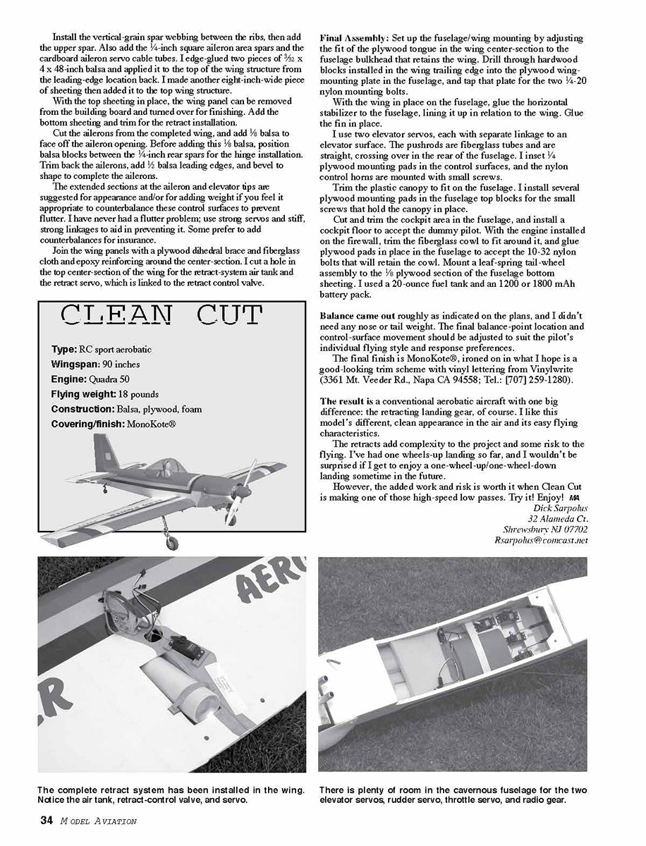
I use two elevator servos, each with separate linkage to an elevator surface. The pushrods are fiberglass tubes and are straight, crossing over in the rear of the fuselage. I insert 1/4 plywood mounting pads in the control surfaces, and the nylon control horns are mounted with small screws.
Trim the plastic canopy to fit on the fuselage. I install several plywood mounting pads in the fuselage top blocks for the small screws that hold the canopy in place.
Cut and trim the cockpit area in the fuselage, and install a cockpit floor to accept the dummy pilot. With the engine installed on the firewall, trim the fiberglass cowling to fit around it, and glue plywood pads in place in the fuselage to accept the 10-32 nylon bolts that will retain the cowl. Mount a leaf-spring tail-wheel assembly to the 1/8 plywood section of the fuselage bottom sheeting. I used a 20-ounce fuel tank and a 1200 or 1800 mAh battery pack.
Balance came out roughly as indicated on the plans, and I didn't need any nose or tail weight. The final balance-point location and control-surface movement should be adjusted to suit the pilot's individual flying style and response preferences.
The final finish is MonoKote®, ironed on in what I hope is a good-looking trim scheme with vinyl lettering from Vinylwrite (3361 Mt. VedeR Rd., Napa CA 94558; Tel.: [707] 259-1280).
The result is a conventional aerobatic aircraft with one big difference: the retracting landing gear, of course. I like this model's different, clean appearance in the air and its easy flying characteristics.
The retracts add complexity to the project and some risk to the flying. I've had one wheels-up landing so far, and I wouldn't be surprised if I get to enjoy a one-wheel-up/one-wheel-down landing sometime in the future.
However, the added work and risk is worth it when Clean Cut is making one of those high-speed low passes. Try it! Enjoy!
— Rick Sarpalus 32 Alameda Ct. Shrewsbury, NJ 07702 [email protected]
Type: RC sport aerobatic Wingspan: 90 inches Engine: Quadra 50 Flying weight: 18 pounds Construction: Balsa, plywood, foam Covering/finish: MonoKote®
The complete retract system has been installed in the wing. Notice the air tank, retract-control valve, and servo.
There is plenty of room in the cavernous fuselage for the two elevator servos, rudder servo, throttle servo, and radio gear. ACE, HOW ABOUT A BIG MUG OF FROSTY COLD LEMONADE?
SOUNDS GREAT! DO I HAVE TO MOVE SO WILBUR CAN COME TO ME? Full-Size Plans Available—see page 191
(Note: No additional article text for "Clean Cut" appears on this scanned page; it contains full-size plans/diagrams only.)
Transcribed from original scans by AI. Minor OCR errors may remain.

