
CONTROL LINE AEROBATICS - 2001/01
Frank McMillan, 12106 Gunter Grove, San Antonio, TX 78231
THIS MONTH I'll discuss heat, and how it affects your engine.
I may not cover each circumstance, because there are so many different combinations that can combine to create problems. Likewise, you can make a series of errors that are bad enough in the short term to hurt the engine run.
However, this discussion is extremely important; if you want your equipment to perform the way it should, read on.
Engine mounting and cooling — general
Probably the most important factor in a stunt engine that runs well is a stable mounting system.
The mounting surface should be flat, and the engine should mate perfectly to that surface. The surface should be a hard material, such as aluminum or phenolic, to transfer load, heat, and vibration, and should last indefinitely. There must be sufficient mass to absorb and transfer vibration to the main structure.
The design of the internal structure should be carefully analyzed to ensure that it has a direct line to the exterior skin of the airplane. If you don't examine this, you can expect a stress crack where the continuity stops.
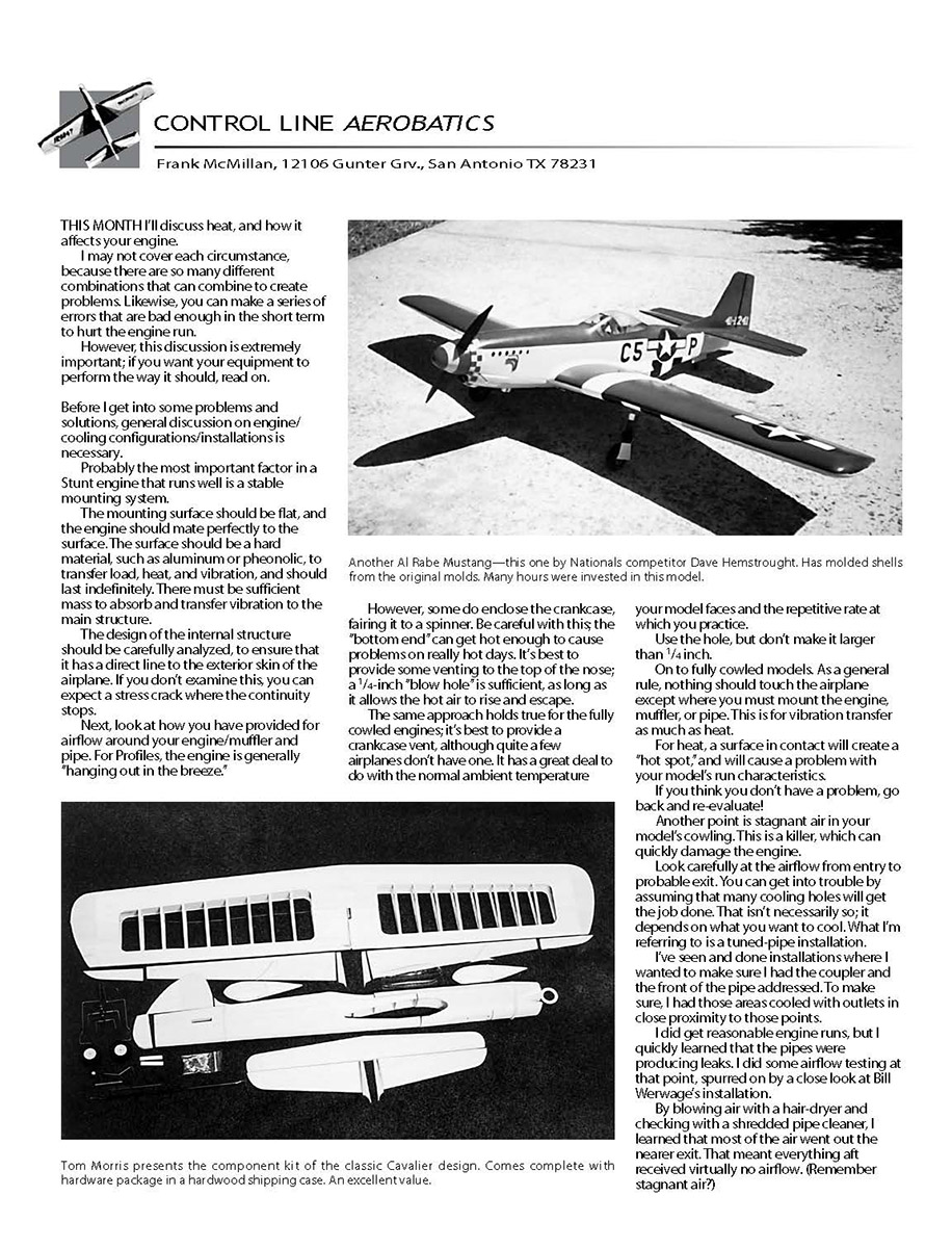
Next, look at how you have provided for airflow around your engine, muffler, and pipe. For profiles, the engine is generally "hanging out in the breeze." However, some enclose the crankcase, fairing it to a spinner. Be careful with this; the bottom end can get hot enough to cause problems on really hot days. It's best to provide some venting to the top of the nose; a 1/4-inch "blow hole" is sufficient, as long as it allows the hot air to rise and escape.
The same approach holds true for fully cowled engines: it's best to provide a crankcase vent, although quite a few airplanes don't have one. It has a great deal to do with the normal ambient temperature your model faces and the repetitive rate at which you practice. Use the hole, but don't make it larger than 1/4 inch.
Cowling and airflow
As a general rule, nothing should touch the airplane except where you must mount the engine, muffler, or pipe. This is for vibration transfer as much as heat. For heat, a surface in contact will create a hot spot and will cause a problem with your model's run characteristics. If you think you don't have a problem, go back and re-evaluate.
Another point is stagnant air in your model's cowling. This is a killer and can quickly damage the engine.
Look carefully at the airflow from entry to probable exit. You can get into trouble by assuming that many cooling holes will get the job done. That isn't necessarily so; it depends on what you want to cool. What I'm referring to is a tuned-pipe installation.
Tuned-pipe installations and airflow testing
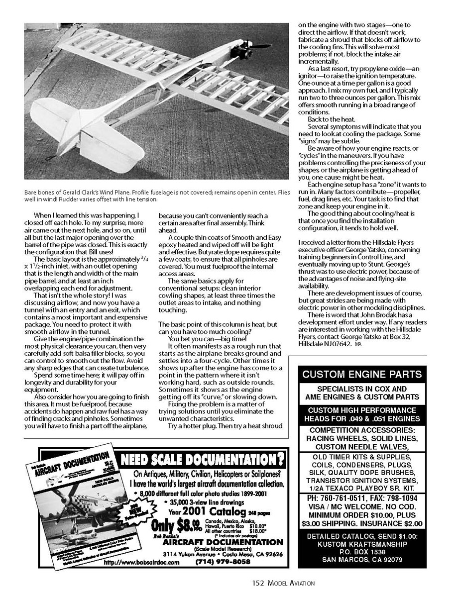
I've seen and done installations where I wanted to make sure I had the coupler and the front of the pipe addressed. To make sure, I had those areas cooled with outlets in close proximity to those points. I did get reasonable engine runs, but I quickly learned that the pipes were producing leaks. I did some airflow testing at that point, spurred on by a close look at Bill Werwage's installation.
By blowing air with a hair dryer and checking with a shredded pipe cleaner, I learned that most of the air went out the nearer exit. That meant everything aft received virtually no airflow. (Remember stagnant air?)
When I learned this was happening, I closed off each hole. To my surprise, more air came out the next hole, and so on, until all but the last major opening over the barrel of the pipe was closed. This is exactly the configuration that Bill uses!
The basic layout is:
- Approximately a 3/4 x 1 1/2-inch inlet.
- An outlet opening that is the length and width of the main pipe barrel, with at least an inch overlapping each end for adjustment.
That's not the whole story. You now have a tunnel with an entry and an exit that contains a most important and expensive package. You need to protect it with smooth airflow in the tunnel.
Give the engine/pipe combination the most physical clearance you can, then very carefully add soft balsa filler blocks so you can smooth out the flow. Avoid any sharp edges that can create turbulence.
Spend some time here; it will pay off in longevity and durability for your equipment.
Finishing and fuelproofing
Also consider how you are going to finish this area. It must be fuelproof, because accidents do happen and raw fuel has a way of finding cracks and pinholes. Sometimes you will have to finish a part off the airplane because you can't conveniently reach a certain area after final assembly. Think ahead.
A couple of thin coats of Smooth & Easy epoxy, heated and wiped off, will be light and effective. Butyrate dope requires quite a few coats to ensure that all pinholes are covered. You must fuelproof the internal access areas.
The same basics apply for conventional setups: clean interior cowling shapes, at least three times the outlet area to intake, and nothing touching.
Can you have too much cooling?
The basic point of this column is heat, but can you have too much cooling? You bet you can—big time.
It often manifests as a rough run that starts as the airplane breaks ground and settles into a four-cycle. Other times it shows up after the engine has come to a point in the pattern where it isn't working hard, such as outside rounds. Sometimes it shows as the engine getting off its curve, or slowing down.
Fixing the problem is a matter of trying solutions until you eliminate the unwanted characteristics. Suggested sequence:
- Try a hotter glow plug.
- Add a heat shroud on the engine in two stages—one to direct the airflow.
- If that doesn't work, fabricate a shroud that blocks off airflow to the cooling fins. This will solve most problems.
- If needed, block the intake air incrementally.
- As a last resort, try propylene oxide (an oxidizer/ignitor) to raise the ignition temperature: one ounce at a time per gallon is a good approach. I mix my own fuel and typically run two to three ounces per gallon; this mix offers smooth running in a broad range of conditions.
Signs that you need to address heat
Several symptoms indicate you need to look at cooling the package. Some signs may be subtle.
Be aware of how your engine reacts, or cycles, in the maneuvers. If you have problems controlling the preciseness of your shapes, or the airplane is getting ahead of you, one cause might be heat.
Each engine setup has a zone it wants to run in. Many factors contribute—propeller, fuel, drag lines, etc. Your task is to find that zone and keep your engine in it.
The good thing about cooling/heat is that once you find the installation configuration, it tends to hold well.
Note on electric power for beginners
I received a letter from the Hillsdale Flyers executive officer George Yatsko concerning training beginners in control line and eventually moving up to stunt. George's thrust was to use electric power because of the advantages of noise and flying-site availability.
There are development issues, of course, but great strides are being made with electric power in other modeling disciplines.
There is word that John Brodak has a development effort under way. If any readers are interested in working with the Hillsdale Flyers, contact George Yatsko at Box 32, Hillsdale, NJ 07642.
Transcribed from original scans by AI. Minor OCR errors may remain.

