
CONTROL LINE AEROBATICS
Frank McMillan, 12106 Gunter Grove, San Antonio TX 78231
As I think about many columns of the past, I realize that I've fiddled with the numbers game many times. However, it's about time I focused on a few points that will "eat your lunch" if you're not careful. I'm referring to how measurements and dimension control during the construction process can combine to affect your model's flight performance. Although this discussion may seem a bit esoteric to some readers, you may run into many of these situations.
Let's talk about controlling shapes. You want to make sure you have an accurate representation of the part you want to make. The stabilizer that is symmetrical about the centerline needs to be symmetrical. It seems so obvious that it should be a given, but think again. When drawing up new stabilizers (stabs), more than once I have copied the original drawing for a pattern and found an error side-to-side; the leading edge on one side was a pencil-width less. I caught the error by folding the pattern on the centerline. Now you could ask, "How much could that minor error have affected flight characteristics?" The answer is, "Probably not much." However, if undiscovered, the error could be multiplied as the pattern was transferred. The nature of these errors is that they multiply if you're not careful. That's really the problem I'm highlighting: the need to be exceptionally accurate in every stage of constructing a model.
Consider the stage at which you have accurately constructed the stab, and now you have to shape the leading and trailing edges. As you shape, you remove material. It takes discipline and a good eye to produce the desired radii and straight lines. Once you've done that, do you go back to see if your planform was maintained (accurately)? It's a good idea to check how well you've done!
While we're at the construction sampling stage, have you checked thickness? I've seen stabs that were true, but one side was thicker than the other. That can affect how the airplane flies, because thickness equals lift. There could be several causes for that. The thickness of the wood sheets might be inconsistent and not what is represented. When a design calls for 1/16-inch thickness, do you have that exact thickness? Does it matter? Most times it doesn't, as long as you know. However, if you are concerned with a target thickness, such as the target stab thickness of 9/16-inch, you should check. Be aware that multiple layers of materials can add to the errors, and that is the numbers game. If you check, you might even take advantage of sheeting with uneven thickness to adjust the total thickness of a part from one side to the other.
Another cause of inaccuracy could be you. When you sand the framework of any part, you have to be careful about thickness. Visualize a symmetrical airfoil on a stab. There is a centerline and a shape to maintain. It's obvious that the airfoil must be maintained, and it should be symmetrical about the centerline. The experienced builder would say that he or she can construct the model with a plotted section copied from plans, and there's that point again: yes, you can, but again, you have to watch the sanding. If you do too much to smooth the mating of the ribs, you change the thickness on one of the four surfaces. That changes the lift symmetry of the stab.
Another area to look at is the edges of your control surface. The radii should be the same surface-to-surface; i.e., right-to-left stab, right-to-left elevator. Everything should be identical. Here's where you run into trouble. As you shape the planform, you can blunt the edges but induce a difference in the thickness. To correct this, you have to thin the edge to get the radius to the dimension you want. It's all a circle of interrelationships!
In the big picture, the details I've discussed are relatively minor by themselves. But if you don't understand how and why you can experience them, you will probably make these mistakes. I know, because I've made all these errors and then some.
Many of the "not-so-good" models have problems rooted in the myriad of details encountered in constructing a good-flying stunter.
You should be aware of all the things that can go wrong. Armed with the knowledge, you can develop your building skills and procedures to avoid potential problems.
New Items:
If you're going to do good work, you need good tools. You can tell quality by the feel and balance, and by the smoothness of operation.
For some time, I'd heard about the Eclipse HP-BCS bottle-feed airbrush. I recently had the opportunity to test several of the extensive line of tailored instruments. From the first moment you pick one of these tools up, you know you've got quality in your hands.
The Eclipse HP-BCS bottle-feed airbrush is dual action, with the control button regulating the material flow and the air. This gives exceptional control for the finest detail. On the other end of the demand scale, the airbrush is also designed for high paint flow with thin to thick paints, right in the range for our use.
The other gun I tried, which fits into the next-larger category, is the RG-2. The most impressive aspect of this gun is the detail of the design. The control needle is supported by multiple bearings, to ensure smooth operation and long life. This is the right-size gun to touch up the main coats on our airplanes. The advantage is that you can control the paint flow to produce extremely thin, uniform coats. This results in easier finishing and lighter weight.
- Eclipse HP-BCS bottle-feed airbrush
- Dual action: controls material flow and air
- Excellent for finest detail and for high paint flow with a range of viscosities
- RG-2
- Multiple-bearing supported control needle for smooth operation and long life
- Good for touching up main coats with extremely thin, uniform layers
Both units are first class, and together are all we need in capability and quality. Give these a look if you're in the market or want to upgrade. Contact Iwata-Medea, 795 SE Taylor St., Portland OR 97214; Tel.: (503) 253-7308.
The exceptional PA .65 is now in more fliers' hands. The limits of its flexible power are being explored, with larger propellers and more blades. This engine is a real "horse" that likes more and more load.
We were using the 13 x 4-1/4 Bolly blade until recently, and it was great! Now Randy Smith, the PA designer and supplier, has a new extended 13-1/2 x 4-1/4. Diameter is critical, so you can derive some huge benefits if your engine can carry the diameter.
As a rule of thumb, each 1/8-inch addition in diameter in this range is approximately a 2% change.
Remember that increasing diameter does slow the turn; you must experiment. You can also fly slower with increased diameter, because you have the thrust.
Contact Randy at Aero Products, 1880 Scenic Hwy., Snellville GA 30278; Tel.: (770) 979-2045.
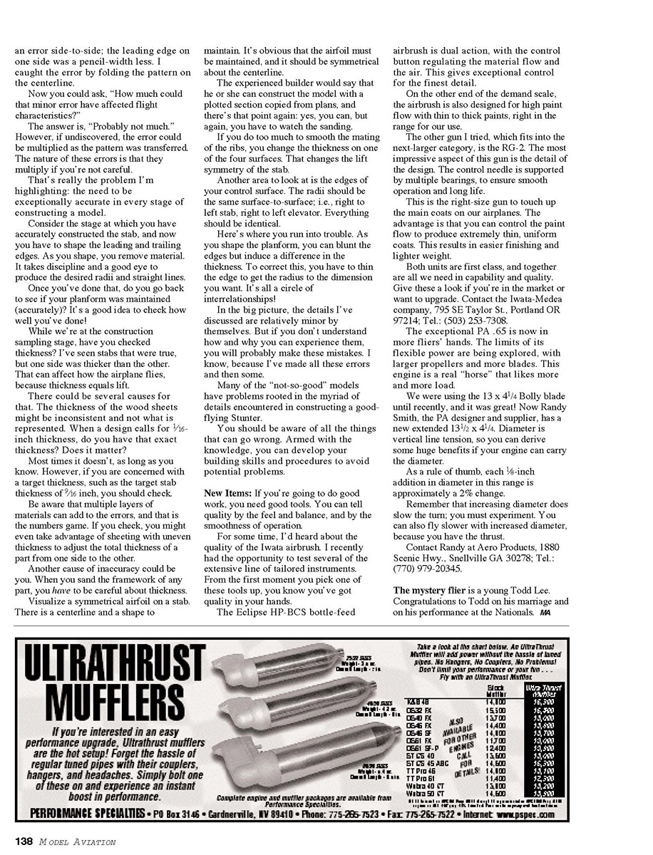
The mystery flier is a young Todd Lee. Congratulations to Todd on his marriage and on his performance at the Nationals. MA
Transcribed from original scans by AI. Minor OCR errors may remain.

