
CONTROL LINE AEROBATICS
Curt Contrata, 6783 Nightwind Cir., Orlando FL 32818; E-mail: [email protected]
Tanks seem to leak at the worst time—usually when you are at a contest. For this reason, it is a good idea to have a flight‑tested tank standing by at all times. But even with a spare tank, it is not always easy to make the switch; it depends on the method of installation. In fact, the potential of a tank leak can increase or decrease with the method of installation.
For several seasons I mounted my tanks using a bolt through the middle of each. I loved how easy it was to change a leaking tank. This was good because tanks using this method will eventually leak. I remember one particular Nats during which Gene Martine helped me repair a leaking tank each evening. Night after night, he would preach about the way he mounted his tanks.
I switched from using a single bolt through the middle to using clear silicone and balsa strips to hold the tank in place. I also used silicone to glue the tank vents in place where they exited the fuselage. This helped support the vents and reduced their vibration and the chances that the vents' solder joints would fail. Tanks mounted this way never seemed to leak. There was no stress on the tank, and it could not move. It was also a lighter method than using a bolt.
The downside was that when a tank did leak, or if you needed to make an adjustment, the repair and swap were more difficult. Another bummer was that neither a tank adjustment nor a replacement was practical at the field because of the silicone's drying time. I have been forced to fly at a contest with a leaking tank because of the time it would have taken for the silicone to cure. Gene preached again, and I finally listened.
Simple clip-and-bracket method (no tank mods)
Gene's method is simple and requires no special tools or skills. No modifications need to be made to the tank, so an off‑the‑shelf replacement drops right in. Tank‑mounting methods that require pieces to be soldered onto the tank not only make it custom, but they are added points of failure. Besides, if your tank is stock, there are spares available everywhere.
By using two small strips of basswood and a few small drops of thick cyanoacrylate glue to lock everything in place, field height adjustment and tank replacement are possible—even between rounds. Not being one who likes to overcomplicate things, I endorse this method for its simplicity and functionality.
Materials
- A few inches of 1/8‑inch basswood.
- 1/2‑inch‑wide double‑stick foam tape (several layers as needed).
- Thick cyanoacrylate (CA) glue.
- Small scrap of 1/4‑inch balsa for a spacer.
- Optional: small dab of silicone where clips touch the tank.
Parts overview
- Part A: the clip (2 required).
- Part B: the bracket (4 required).
- All parts are made from 1/8‑inch basswood.
Approximate dimensions (see diagram for shape)
- Clip A (2 required): features with dimensions shown as 3/4", 1/2", 1", overall length 2 1/8"*.
- Bracket B (4 required): features shown as 1/8" and 1/4".
*This overall length should be 1/16 inch less than the width of the tank compartment.
Installation steps
- Drop the tank into the fuselage without tank shims.
- Lay a scrap piece of 1/4‑inch balsa on top of the tank; this spacer's thickness will determine the maximum amount of tank height adjustment you will have (less 1/16 inch).
- Position the two clips on top of the spacer, approximately one‑third of the way from each end of the tank.
- Before gluing the brackets in place, make sure they face the proper direction. Both sets of brackets should be positioned so both clips can be slid toward the center of the tank for installation and removal. This is important since you may be unable to remove the clips if the brackets are facing the spinner or the tail.
- Glue the brackets permanently inside the model. Be careful not to accidentally glue in the clips, or you will have a problem.
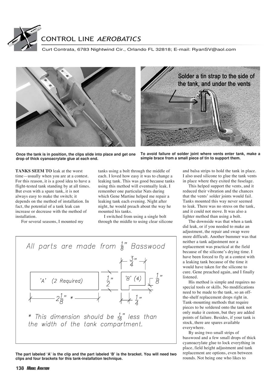
- Apply the foam double‑stick tape to the underside of the clips (the side that will face the tank). The tape is approximately 1/16‑inch thick; with a 1/16‑inch shim under my tank, I used three layers of tape under each clip. Let the layers stick to each other, but do not remove the paper backing on the last layer that will touch the tank—the clip needs to slide into position and should not be stuck to the tank.
- Since the tank is slightly narrower than the fuselage, you can use foam tape on the sides of the tank to fill side play. Leave the paper backing on any tape that will touch the fuselage.
- To get the tank into position, start by sliding the fuel pickup through the firewall; keep the tank rotated slightly as you set it down into the compartment. Once in place, rotate it on the axis of the fuel pickup so it clears the brackets. The spacer gives the extra room needed to rotate the tank past the brackets and into position.
- With the tank in position, slide one clip under a bracket. It should be snug but must not crush the tank. Slide the second clip into position.
- Place one small drop of thick CA glue on each end of each clip to keep it in place. When you need to remove the tank, press down lightly on each end of each clip; you will hear a snap as the CA breaks loose, allowing the clip to slide out.
- As a precaution, place one small dab of silicone where each clip touches the tank to keep the tank from moving during flight.
Reinforcing vent joints
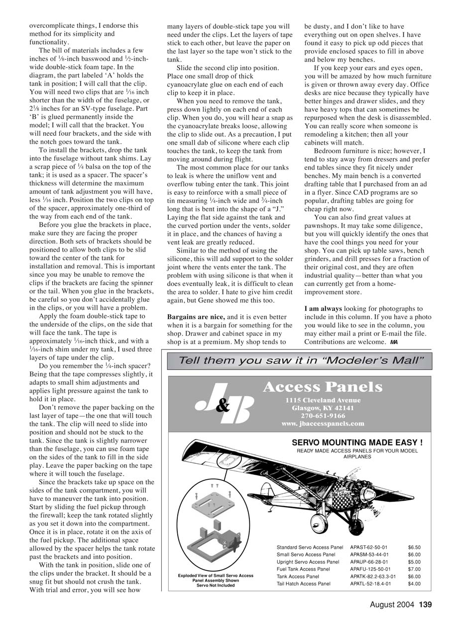
The most common place for tanks to leak is where the uniflow vent and overflow tubing enter the tank. This joint is easy to reinforce with a small piece of tin about 1/4‑inch wide and 3/4‑inch long, bent into the shape of a "J." Lay the flat side against the tank and the curved portion under the vents, then solder it in place. The chances of a vent leak are greatly reduced.
Similar to the silicone method, this adds support to the solder joint where the vents enter the tank. The problem with using silicone is that when it eventually leaks, it is difficult to clean the area for soldering. Gene showed me this too.
SHOP BARGAINS AND STORAGE
Bargains are nice, and it's even better when they help your shop. Drawer and cabinet space in my shop is at a premium. My shop tends to be dusty, and I don't like to have everything out on open shelves. I have found it easy to pick up odd pieces of furniture that provide enclosed spaces to fill in above and below my benches.
If you keep your ears and eyes open, you will be amazed by how much furniture is given away or thrown out every day. Office desks are nice because they typically have better hinges and drawer slides, and they have heavy tops that can sometimes be repurposed when the desk is disassembled. You can really score when someone is remodeling a kitchen; then all your cabinets will match.
Bedroom furniture is nice; however, I tend to stay away from dressers and prefer end tables since they fit nicely under benches. My main bench is a converted drafting table that I purchased from an ad in a flyer. Since CAD programs are so popular, drafting tables are going for cheap right now.
You can also find great values at pawnshops. It may take some diligence, but you will quickly identify the ones that have the cool things you need for your shop. You can pick up table saws, bench grinders, and drill presses for a fraction of the original cost, and they are often industrial quality—better than what you can currently get from a home‑improvement store.
I am always looking for photographs to include in this column. If you have a photo you would like to see in the column, you may either mail a print or e‑mail the file. Contributions are welcome.
MA
Transcribed from original scans by AI. Minor OCR errors may remain.

