
The CL Stunt power package reviewed and explained
P.T. Granderson [email protected]
Also included in this column:
- An engine break-in procedure
WHAT'S NEW?
It just so happens that there is something new in Precision Aerobatics (Stunt). In fact, it may change the way we do things forever.
For as long as I can remember, the big mystery in Stunt has been power. Through the years there have been many solutions and methods of getting an acceptable power system to work consistently. The last significant improvement to the power systems in general was the tuned pipe. For the majority of top competitors in the US, a good tuned-pipe system is a "must-have."
The other big thing has been the availability of engines that have either been designed specifically for our purpose or can easily be adapted for the rigors of Stunt. As these engines have been put into operation, many people have begun to modify and tweak them for a variety of reasons.
So how do you begin to put the power puzzle together?
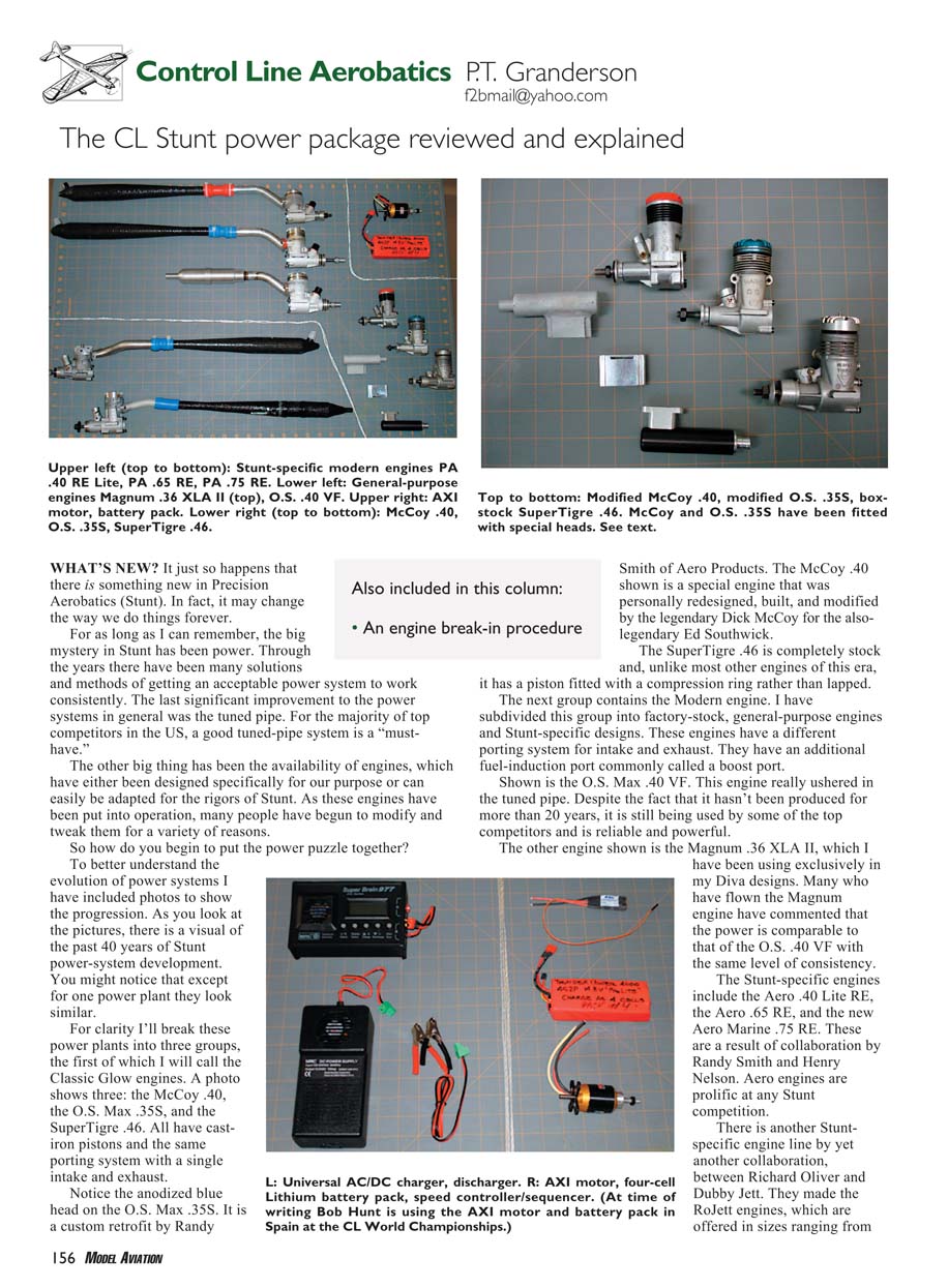
To better understand the evolution of power systems I have included photos to show the progression. As you look at the pictures, there is a visual of the past 40 years of Stunt power-system development. You might notice that, except for one power plant, they look similar.
For clarity I'll break these power plants into three groups.
Classic Glow engines
A photo shows three representative engines: the McCoy .40, the O.S. Max .35S, and the SuperTigre .46. All have cast-iron pistons and the same porting system with a single intake and exhaust.
Notice the anodized blue head on the O.S. Max .35S. It is a custom retrofit by Randy Smith of Aero Products. The McCoy .40 shown is a special engine that was personally redesigned, built, and modified by the legendary Dick McCoy for the also-legendary Ed Southwick. The SuperTigre .46 is completely stock and, unlike most other engines of this era, it has a piston fitted with a compression ring rather than lapped.
Modern engines
I have subdivided this group into factory-stock, general-purpose engines and Stunt-specific designs. These engines have a different porting system for intake and exhaust and include an additional fuel-induction port commonly called a boost port.
Shown is the O.S. Max .40 VF. This engine really ushered in the tuned pipe. Despite the fact that it hasn't been produced for more than 20 years, it is still being used by some of the top competitors and is reliable and powerful. The other engine shown is the Magnum .36 XLA II, which I have been using exclusively in my Diva designs. Many who have flown the Magnum engine have commented that the power is comparable to that of the O.S. .40 VF with the same level of consistency.
The Stunt-specific engines include the Aero .40 Lite RE, the Aero .65 RE, and the new Aero Marine .75 RE. These are the result of collaboration between Randy Smith and Henry Nelson. Aero engines are prolific at any Stunt competition.
There is another Stunt-specific engine line from a collaboration between Richard Oliver and Dubby Jett. They made the RoJett engines, which are offered in sizes ranging from the RoJett .40 to the RoJett .85.
Electric power (motor systems)
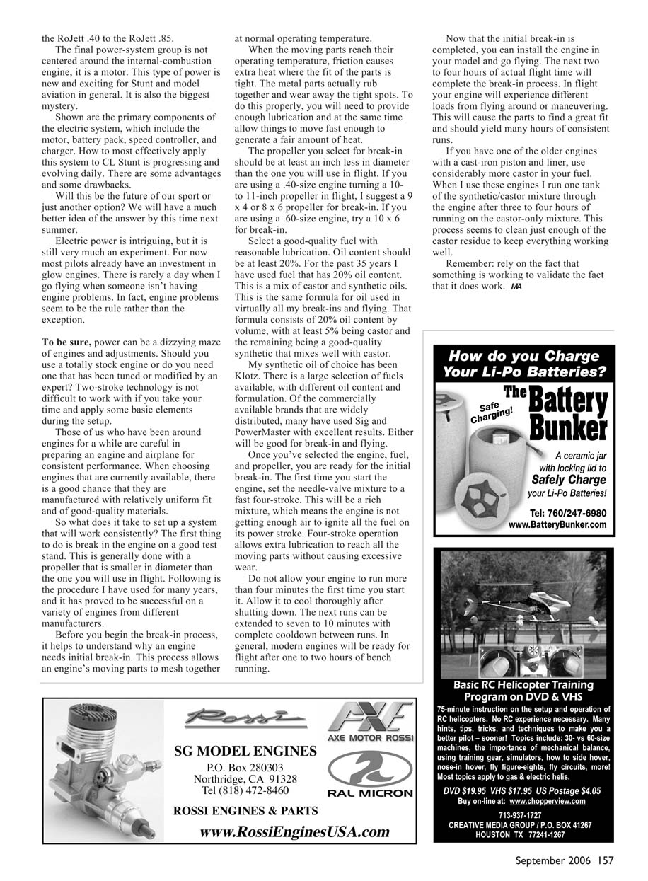
The final power-system group is not centered around the internal-combustion engine; it is based on an electric motor. This type of power is new and exciting for Stunt and model aviation in general. It is also the biggest mystery.
Primary components of the electric system include:
- Motor
- Battery pack
- Speed controller (ESC)
- Charger
How to most effectively apply this system to CL Stunt is progressing and evolving daily. There are some advantages and some drawbacks.
Will this be the future of our sport or just another option? We will have a much better idea of the answer by this time next summer.
Electric power is intriguing, but it is still very much an experiment. For now most pilots already have an investment in glow engines. There is rarely a day when I go flying when someone isn't having engine problems. In fact, engine problems seem to be the rule rather than the exception.
To be sure, power can be a dizzying maze of engines and adjustments. Should you use a totally stock engine or do you need one that has been tuned or modified by an expert? Two-stroke technology is not difficult to work with if you take your time and apply some basic elements during the setup.
Those of us who have been around engines for a while are careful in preparing an engine and airplane for consistent performance. When choosing engines that are currently available, there is a good chance that they are manufactured with relatively uniform fit and of good-quality materials.
Engine break-in procedure
So what does it take to set up a system that will work consistently? The first thing to do is break in the engine on a good test stand. This is generally done with a propeller that is smaller in diameter than the one you will use in flight. Following is a procedure I have used for many years, and it has proven successful on a variety of engines from different manufacturers.
Why break in an engine?
Before you begin the break-in process, it helps to understand why an engine needs initial break-in. This process allows an engine's moving parts to mesh together at normal operating temperature.
When the moving parts reach their operating temperature, friction causes extra heat where the fit of the parts is tight. The metal parts actually rub together and wear away the tight spots. To do this properly, you need to provide enough lubrication and at the same time allow things to move fast enough to generate a fair amount of heat.
Propeller selection for break-in
- Select a propeller at least an inch less in diameter than the one you will use in flight.
- Example: If you are using a .40-size engine turning a 10- to 11-inch propeller in flight, use a 9 x 4 or 8 x 6 propeller for break-in.
- Example: If you are using a .60-size engine, try a 10 x 6 prop for break-in.
Fuel selection
Select a good-quality fuel with reasonable lubrication. Oil content should be at least 20%.
- I have used fuel with 20% oil content for the past 35 years.
- My mix is 20% oil by volume, with at least 5% being castor and the remainder a good-quality synthetic oil that mixes well with castor.
- My synthetic oil of choice has been Klotz.
- Commercially available fuels such as Sig and PowerMaster work well for break-in and flying.
Break-in steps
- Install the smaller break-in propeller on a secure test stand.
- Set the needle-valve mixture to a fast four-stroke on the very first start. This is a rich mixture (engine not getting enough air to ignite all the fuel on its power stroke). Four-stroke operation allows extra lubrication to reach moving parts without causing excessive wear.
- Do not allow the engine to run more than four minutes the first time you start it. Allow it to cool thoroughly after shutting down.
- Subsequent runs can be extended to seven to ten minutes, with complete cooldown between runs.
- In general, modern engines will be ready for flight after one to two hours of bench running.
- After the initial bench break-in, install the engine in your model and go flying. The next two to four hours of actual flight time will complete the break-in process. In flight the engine will experience different loads from maneuvering, which helps the parts find their best fit and yields many hours of consistent runs.
Notes for older engines
If you have one of the older engines with a cast-iron piston and liner, use considerably more castor in your fuel. When I use these engines I run one tank of a synthetic/castor mixture through the engine after three to four hours of running on a castor-only mixture. This process seems to clean just enough of the castor residue to keep everything working well.
Remember: rely on the fact that something is working to validate the fact that it does work. MA
Transcribed from original scans by AI. Minor OCR errors may remain.

