
Control Line Aerobatics
Bob Hunt [[email protected]]
The Hole Shot project continues with the tail feathers
(Editor’s note: You can follow along with your own profile Hole Shot or get a set of plans for it. Randy Smith at Aero Products has plans and foam wing cores available for this and other great Aerobatics trainers.)
In the last column we brought the Hole Shot’s fuselage to the point where it was ready to accept the wing and tail assemblies. Let’s start this time with constructing the tail feathers.
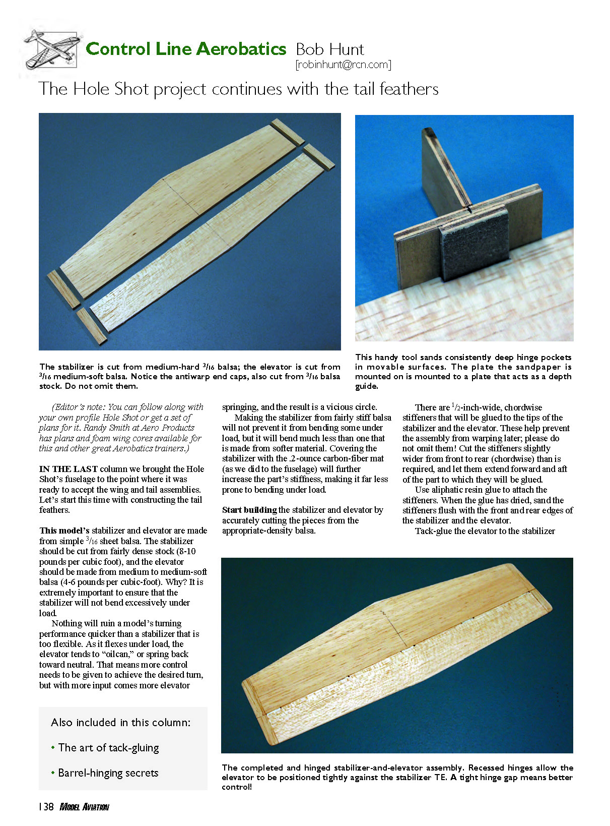
This model’s stabilizer and elevator are made from simple 3/16-inch sheet balsa. The stabilizer should be cut from fairly dense stock (8–10 pounds per cubic foot), and the elevator should be made from medium to medium-soft balsa (4–6 pounds per cubic foot). Why? It is extremely important to ensure that the stabilizer will not bend excessively under load.
Nothing will ruin a model’s turning performance quicker than a stabilizer that is too flexible. As it flexes under load, the elevator tends to “oilcan,” or spring back toward neutral. That means more control needs to be given to achieve the desired turn, but with more input comes more elevator springing, and the result is a vicious circle.
Making the stabilizer from fairly stiff balsa will not prevent it from bending some under load, but it will bend much less than one made from softer material. Covering the stabilizer with the 0.2-ounce carbon-fiber mat (as we did to the fuselage) will further increase the part’s stiffness, making it far less prone to bending under load.
Start building the stabilizer and elevator by accurately cutting the pieces from the appropriate-density balsa.
There are 1/2-inch-wide, chordwise stiffeners that will be glued to the tips of the stabilizer and the elevator. These help prevent the assembly from warping later; please do not omit them! Cut the stiffeners slightly wider from front to rear (chordwise) than is required, and let them extend forward and aft of the part to which they will be glued.
Use aliphatic resin glue to attach the stiffeners. When the glue has dried, sand the stiffeners flush with the front and rear edges of the stabilizer and the elevator.
Tack-glue the elevator to the stabilizer against a flat surface. This will allow you to sand the entire assembly at one time, rounding the LE and TE and the tips. The result will be an assembly that looks like one smooth part when it’s hinged together.
For those of you who are new to building, I just introduced a new term: “tack-glue.” Sometimes you will need to hold two (or more) parts together for carving and sanding, and the best way to do this is to put tiny dots of glue every few inches along the mating seam. The glue will hold the parts together well enough for you to do the required work, and then you carefully flex the assembly to break the glue dots and separate the parts. Sometimes you will be unable to flex an assembly that is tack-glued, and in those instances you will have to use a thin, sharp knife blade to slit the glue dots apart. An example of this would be tack-gluing balsa blocks onto a fuselage crutch assembly for carving and sanding. An assembly that size will not be easy to flex, and you probably shouldn’t try!
Okay, the stabilizer and elevator are tack-glued and sanded to shape. The edges should have an even radius. Take your time here and detail-sand the edges so they blend perfectly with the upper and lower surfaces of the assembly. When you are happy with the shapes of the tips and the LEs and TEs, it's time to lay out the positions of the hinges.
There are several options for hinging the elevator to the stabilizer. Barrel-type hinges that have a pin between the two sections are popular, and they are the type I recommend. You can also use the hinge-point-type hinges or the traditional cloth hinges. To explain the installation of each of these types would take more space than I have left this time, so I'll focus on the barrel variety. I use the Great Planes Medium Nylon Pinned Hinges (part GPMQ3971) on my airplanes.
- Use at least five hinges to attach the elevator to the stabilizer. One hinge should be positioned on the centerline of the assembly, and there should be two more on either side, equally spaced.
- Place the five barrel hinges along the hinge line and space them properly. The outside edges of the outermost hinges should be approximately 1/2 inch in from the end of the assembly.
Once you are happy with the hinge locations, use a soft pencil to make a light tick mark on both sides of each hinge on the stabilizer and the elevator top surfaces. Transfer these mark locations to the elevator LE and the stabilizer TE.
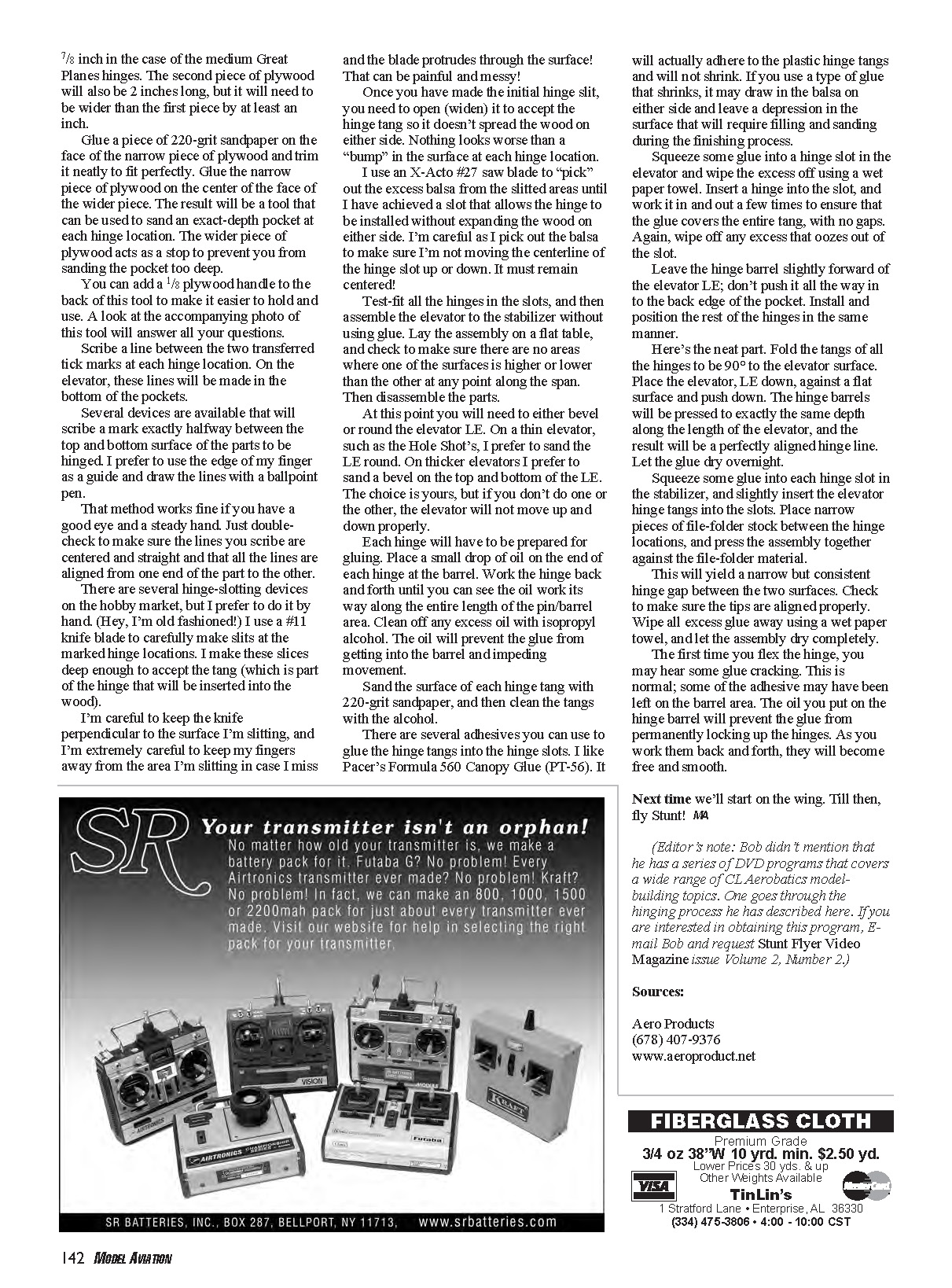
The hinges in the elevator will have to be recessed to allow the elevator LE to almost contact the stabilizer TE when the parts are all assembled. It is imperative that the hinge gap be as tight as possible, while still allowing free movement up and down. Too much gap will allow air to pass through, and the result will be loss of control authority.
To recess the hinges, you will have to make pockets. Mark the positions of these pockets in the elevator LE, and use a #11 knife blade to make a cut at each end of a hinge location that is not quite as deep as will be needed. Carve out some material between these cuts, again being certain not to cut to the depth that will eventually be required.
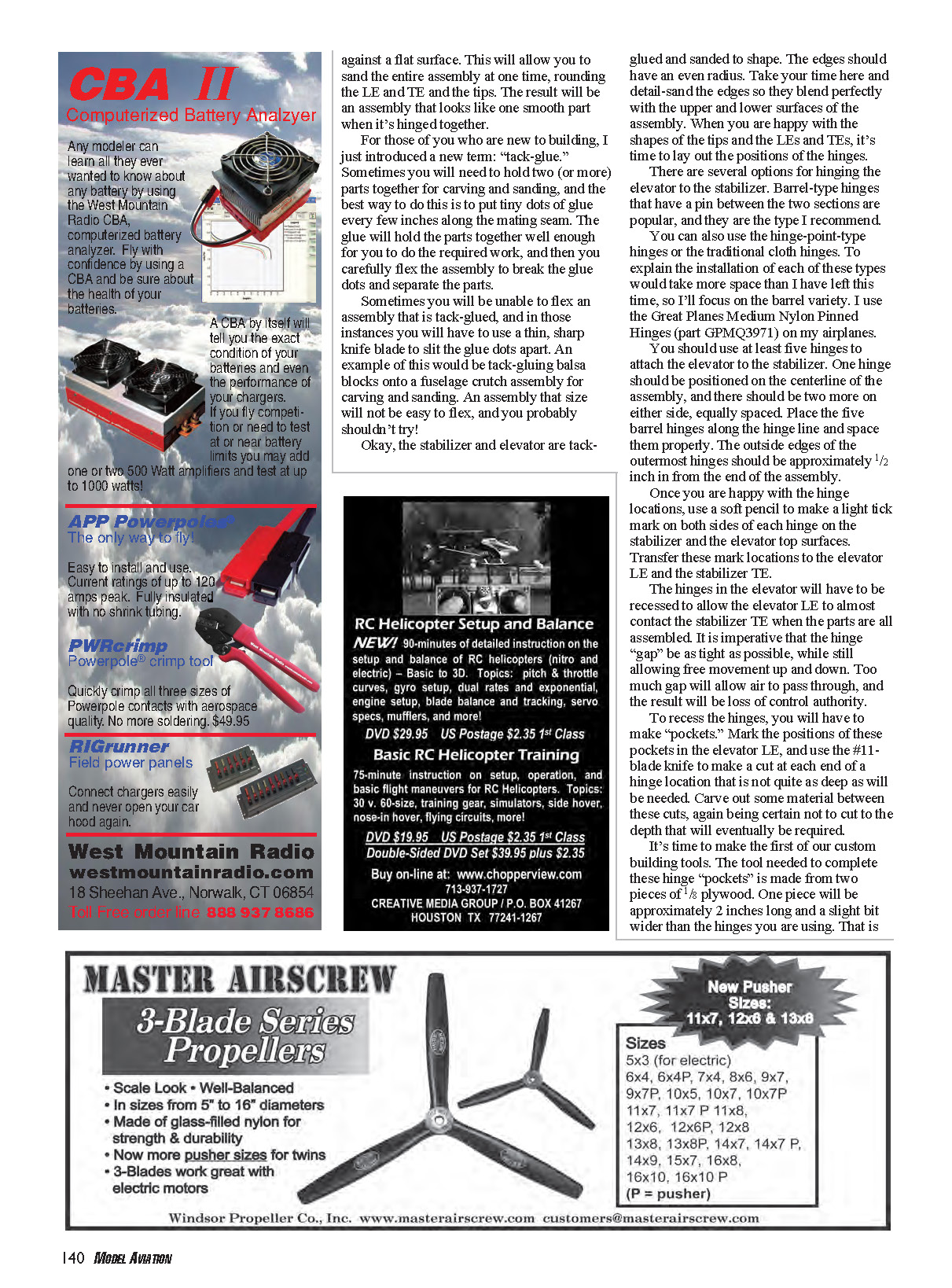
It's time to make the first of our custom building tools. The tool needed to complete these hinge pockets is made from two pieces of 1/8-inch plywood. One piece will be approximately 2 inches long and a slight bit wider than the hinges you are using. That is 7/8 inch in the case of the medium Great Planes hinges. The second piece of plywood will also be 2 inches long, but it will need to be wider than the first piece by at least an inch.
Glue a piece of 220-grit sandpaper on the face of the narrow piece of plywood and trim it neatly to fit perfectly. Glue the narrow piece of plywood on the center of the face of the wider piece. The result will be a tool that can be used to sand an exact-depth pocket at each hinge location. The wider piece of plywood acts as a stop to prevent you from sanding the pocket too deep.
You can add a 1/8-inch plywood handle to the back of this tool to make it easier to hold and use. A look at the accompanying photo of this tool will answer all your questions.
Scribe a line between the two transferred tick marks at each hinge location. On the elevator, these lines will be made in the bottom of the pockets.
Several devices are available that will scribe a mark exactly halfway between the top and bottom surface of the parts to be hinged. I prefer to use the edge of my finger as a guide and draw the lines with a ballpoint pen. That method works fine if you have a good eye and a steady hand. Just double-check to make sure the lines you scribe are centered and straight and that all the lines are aligned from one end of the part to the other.
There are several hinge-slotting devices on the hobby market, but I prefer to do it by hand. I use a #11 knife blade to carefully make slits at the marked hinge locations. I make these slices deep enough to accept the tang (which is part of the hinge that will be inserted into the wood).
Be careful to keep the knife perpendicular to the surface you're slitting, and keep your fingers away from the area you're slitting in case the blade protrudes through the surface.
Once you have made the initial hinge slit, you need to open (widen) it to accept the hinge tang so it doesn't spread the wood on either side. Nothing looks worse than a bump in the surface at each hinge location.
I use an X-Acto #27 saw blade to pick out the excess balsa from the slitted areas until I have achieved a slot that allows the hinge to be installed without expanding the wood on either side. I'm careful as I pick out the balsa to make sure I'm not moving the centerline of the hinge slot up or down. It must remain centered!
Test-fit all the hinges in the slots, and then assemble the elevator to the stabilizer without using glue. Lay the assembly on a flat table, and check to make sure there are no areas where one of the surfaces is higher or lower than the other at any point along the span. Then disassemble the parts.
At this point you will need to either bevel or round the elevator LE. On a thin elevator, such as the Hole Shot's, I prefer to sand the LE round. On thicker elevators I prefer to sand a bevel on the top and bottom of the LE. The choice is yours, but if you don't do one or the other, the elevator will not move up and down properly.
Each hinge will have to be prepared for gluing. Place a small drop of oil on the end of each hinge at the barrel. Work the hinge back and forth until you can see the oil work its way along the entire length of the pin/barrel area. Clean off any excess oil with isopropyl alcohol. The oil will prevent the glue from getting into the barrel and impeding movement.
Sand the surface of each hinge tang with 220-grit sandpaper, and then clean the tangs with alcohol.
There are several adhesives you can use to glue the hinge tangs into the hinge slots. I like Pacer's Formula 560 Canopy Glue (PT-56). It will actually adhere to the plastic hinge tangs and will not shrink. If you use a type of glue that shrinks, it may draw in the balsa on either side and leave a depression in the surface that will require filling and sanding during the finishing process.
Squeeze some glue into a hinge slot in the elevator and wipe the excess off using a wet paper towel. Insert a hinge into the slot, and work it in and out a few times to ensure that the glue covers the entire tang, with no gaps. Again, wipe off any excess that oozes out of the slot.
Leave the hinge barrel slightly forward of the elevator LE; don't push it all the way in to the back edge of the pocket. Install and position the rest of the hinges in the same manner.
Fold the tangs of all of the hinges to be 90° to the elevator surface. Place the elevator, LE down, against a flat surface and push down. The hinge barrels will be pressed to exactly the same depth along the length of the elevator, and the result will be a perfectly aligned hinge line. Let the glue dry overnight.
Squeeze some glue into each hinge slot in the stabilizer, and slightly insert the elevator hinge tangs into the slots. Place narrow pieces of file-folder stock between the hinge locations, and press the assembly together against the file-folder material. This will yield a narrow but consistent hinge gap between the two surfaces. Check to make sure the tips are aligned properly. Wipe all excess glue away using a wet paper towel, and let the assembly dry completely.
The first time you flex the hinge, you may hear some glue cracking. This is normal; some of the adhesive may have been left on the barrel area. The oil you put on the hinge barrel will prevent the glue from permanently locking up the hinges. As you work them back and forth, they will become free and smooth.
Next time we'll start on the wing. Till then, fly Stunt! MA
(Editor's note: Bob didn't mention that he has a series of DVD programs that covers a wide range of CL Aerobatics model-building topics. One goes through the hinging process he has described here. If you are interested in obtaining this program, e-mail Bob and request Stunt Flyer Video Magazine Issue Volume 2, Number 2.)
Sources
- Aero Products
- Phone: (678) 407-9376
- Web: www.aeroproduct.net
Transcribed from original scans by AI. Minor OCR errors may remain.

