
Control Line Aerobatics
Bob Hunt [[email protected]]
Sanding secrets
In the last CL Aerobatics column, I wrote about skinning the Project Hole Shot foam wing cores. The wing skins should be well cured by now, and it’s time to remove the weights and sand smooth the skins and the joint lines between the leading-edge cap pieces and the skins.
Sanding is perhaps the most important building skill and one of the most difficult to master. The proper tools are a must, and I covered this subject in a previous column about this project.
Also included in this column:
- Wingtips
- Control-system installation
To recap, purchase a few of the Great Planes extruded-aluminum Easy-Touch Bar Sanders. They come in several lengths. I recommend the 12-inch-long bars for most work, but I also suggest that you obtain at least one sanding bar that is long enough to span a complete wing half. This will allow you to sand an entire skin at one time and level the surface.
I start sanding the skins using a bar that is fitted with 100-grit, no-load paper. I try to remove any seams and level the skin. If there is any excess glue on the skin’s surface, sand only in one direction to remove the adhesive. If you sand in a back-and-forth motion, you risk pulling a piece of hard, dried glue back under the sanding bar and severely scratching the skin’s surface.
After you have removed any major surface inconsistencies using 100-grit sandpaper, switch to a long sanding bar fitted with 320-grit paper. Work slowly and remove all the scratches that the 100-grit left. It is very important to check your work often while you are sanding. Do this by “candling” the surface of the wing: hold the wing up to an incandescent bulb and bounce the light off its surface as you critically check the entire area for even the slightest imperfection. Work carefully and remember that if the surface is not flat and smooth, the result will show up in the final finish.
Wingtips
The Hole Shot’s wingtips are made from 1/8-inch light plywood (poplar plywood). Place the end of each wing half on the sheet of material and trace around the airfoil. Cut out the tips using a scroll saw. Cut just outside the line to allow some material for sanding when the tip is installed. Draw a centerline on the inside face of each tip plate with a pencil.
This model’s tip weight bolts to the outside of the tip plate. To anchor the tip weight, a 4-40 blind nut must be installed on the inside face of the tip plate before it is glued to the outer wing half. Refer to the plans for the position of the blind nut. It is typically mounted vertically on the centerline of the tip and positioned chordwise at the CG location.
The inside wingtip needs to be slotted to accept the adjustable leadout-guide slider. I used a Brodak leadout-guide slider in my Hole Shot (part BH 760). Refer to the plans for the slot’s position. Install the slider on the inside of the tip, and clearance the foam in the wing to allow the slider to move through its path of travel without hindrance.
Install the outside tip to the wing using aliphatic resin glue, and secure it with strips of masking tape until the adhesive dries. Sand the tip plate to blend with the wing sheeting.
Note that the inside tip is not installed at this time; it will be glued on after the control system has been installed so that the leadouts can be slid through the leadout-guide slider.
Control-System Installation
A few years ago, this part of the process would have required a whole lot more explanation. In the past, control systems were installed using bent-wire pushrods that fit into the output arm of the bellcrank, and the entire system had to be adjusted carefully to ensure smooth movement throughout its travel, with no binding. That has changed in recent times.
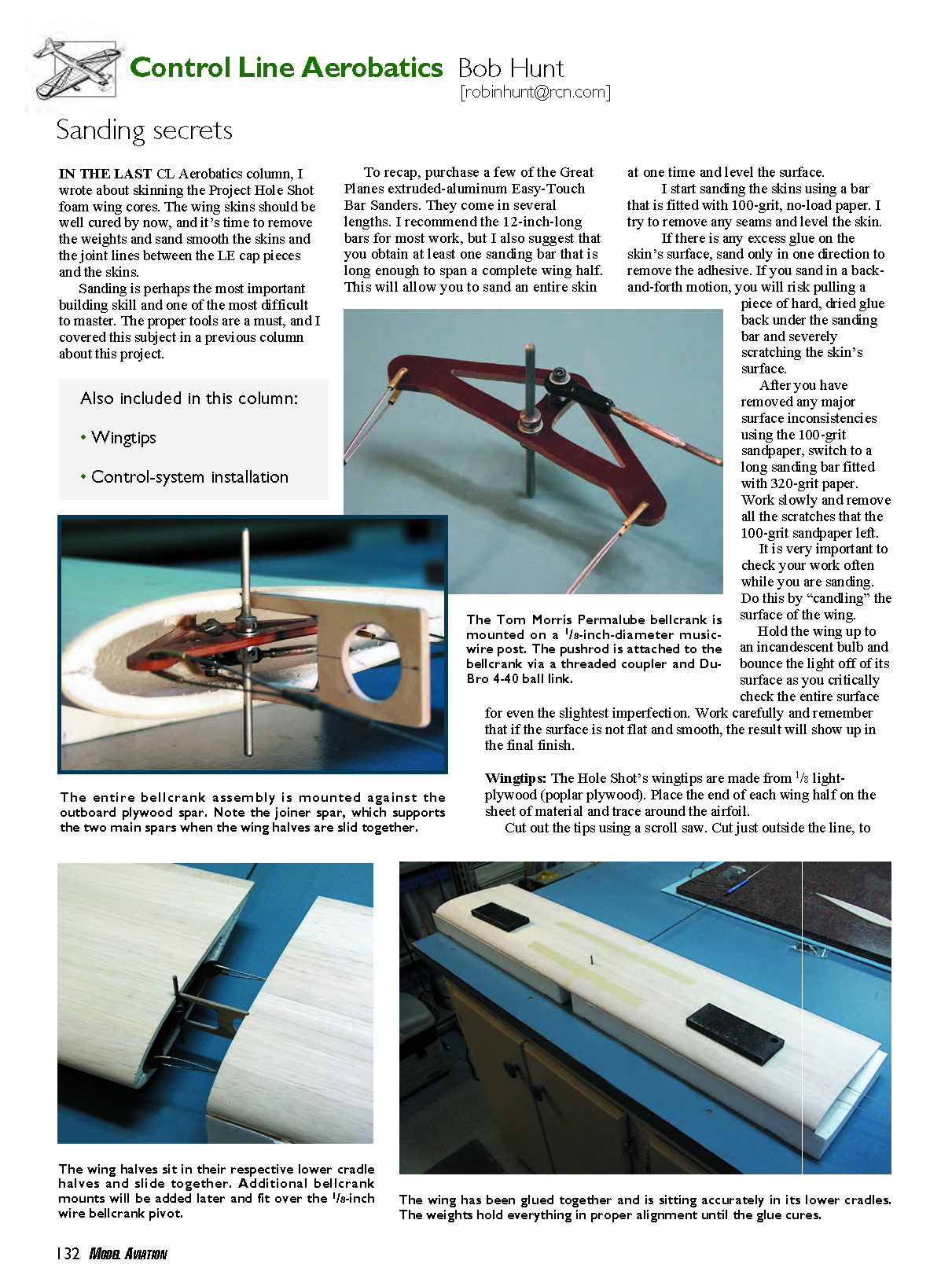
Today, we have ball-link control systems available that require little fiddling. In the Project Hole Shot model, I used the Tom Morris 4-inch Permalube linen-base phenolic bellcrank and Du-Bro 4-40 ball links. The bellcrank comes complete with a mounting kit that is perfect for this application. The bellcrank mounts to a 1/8-inch-diameter wire post.
To begin, insert the 1/8-inch wire post into the bellcrank. Position two washers on the post—one on either side of the bellcrank.
The bellcrank is held in place on the post by two 1/8-inch wheel collars, again on either side of the bellcrank. Slide the bellcrank to the desired position on the post and then tighten the screw in each wheel collar to anchor the bellcrank in place.
A couple of tips: it is never a good idea to rely on just the setscrews in the wheel collars to hold the bellcrank permanently on the round wire post. Vibration can loosen the screws and allow the bellcrank to move, which would be catastrophic in this application.
I suggest you grind or file an extremely shallow flat on the wire so the setscrew seats better than it would against a round surface. Also use a drop of Loctite on the setscrews and apply a fillet of J.B. Weld on the wheel collar/wire-post intersection after you are certain of the bellcrank’s position.
Tom’s bellcranks can be ordered with mil-spec braided (cable) leadout wire already attached, and I recommend purchasing them this way. Where the leadouts pass through their respective holes, Tom uses a piece of annealed brass tubing slid over the wire and bent into a U shape to bush the bellcrank arms.
Braided leadouts have a surface that will act like a saw if not bushed, and the leadout will eventually cut through the bellcrank arm. If you opt to install your own braided leadouts, do not omit the brass tubing bushings.
Some modelers prefer solid-wire leadouts; they can be installed in the bellcrank arms without the need for bushings because their surface is smooth and the phenolic material of the bellcrank provides an excellent bushing for the solid wire.
The pushrod is attached to the bellcrank via a Du-Bro 4-40 Heavy Duty Ball Link (part 760). I prefer to provide a standoff on which to mount the ball link. Sometimes the leadouts will hit the pushrod when the bellcrank is moved through its arc; the standoff helps prevent this. These standoffs are also available from Tom Morris.
Run the 4-40 bolt through the ball link, through the standoff, and into a tapped 4-40 hole in the bellcrank output arm. The bolt should extend through the bottom of the bellcrank hole far enough to allow a 4-40 washer and nut to be attached. After firmly tightening the bolt, apply a fillet of J.B. Weld to the nut and the end of the bolt to prevent it from ever coming loose.
There are two options for a pushrod: you can use either 3/32-inch-diameter music wire or 3/16-inch-diameter carbon tubes (also available from Tom Morris).
If you opt for the carbon-tube method, you can get an entire kit from Tom Morris that includes threaded ends that fit perfectly into the tubes. They are secured in the tubes with J.B. Weld.
If you decide on the 3/32 wire pushrod (as I did with Project Hole Shot), you will need to use a Du-Bro 4-40 threaded coupler that accepts 3/32 wire (part 336). The coupler is soldered to the end of the wire. Be sure to sand and clean the wire so that a good solder joint will result.
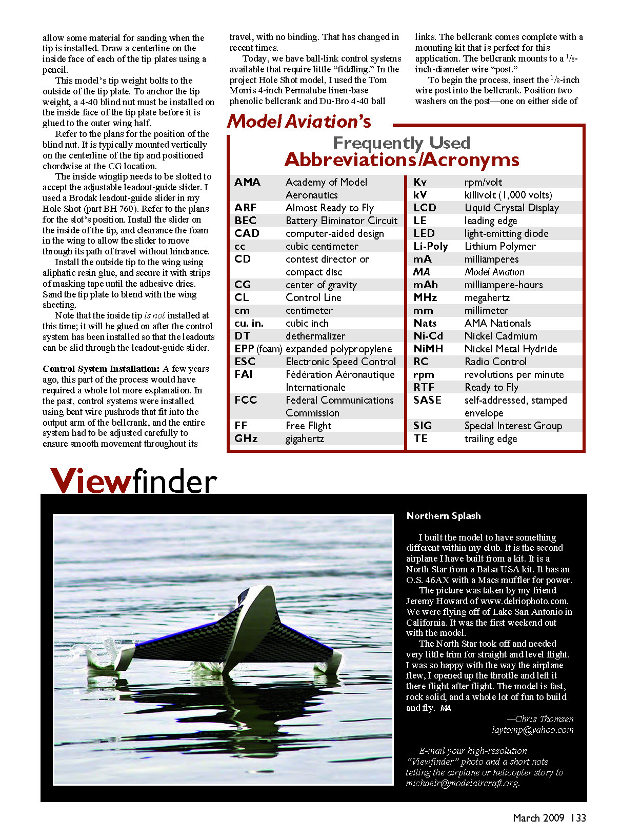
The pushrod post will be positioned in half-round grooves that you will have to file or grind in the root face of the plywood full-depth spars in the foam wing halves.
Position the bellcrank assembly, without the pushrod attached, in the outside wing half and check for any interference as the bellcrank swings through its full travel. If any part of the assembly hits the main spar, remove the assembly and clearance the spar. Continue this procedure until there is no chance of interference with the bellcrank’s movement.
Attach the pushrod to the bellcrank and hold the assembly in place against the outside wing, and move the bellcrank through its full travel. Make tick marks on the outer surface of the wing where it will need to be cleared to allow the pushrod to exit.
I prefer a 3/32 wire pushrod on profile models so I can make a shallow bend in the wire to get it out of the wing where it will be accessible. This is impossible with the carbon pushrod. On larger, full-bodied models, I would opt for the carbon pushrod.
The joiner spar will be glued and slid into the outer wing half as the bellcrank/pushrod assembly is installed. Glue the post into the half-round groove in the outer main spar. You can use medium-viscosity cyanoacrylate glue for this, but be careful not to let any adhesive get on the foam that is on either side of the spar; it will melt the foam. A dab of five-minute epoxy is probably a better bet here.
Set and hold the bellcrank assembly in perfect alignment until the epoxy cures.
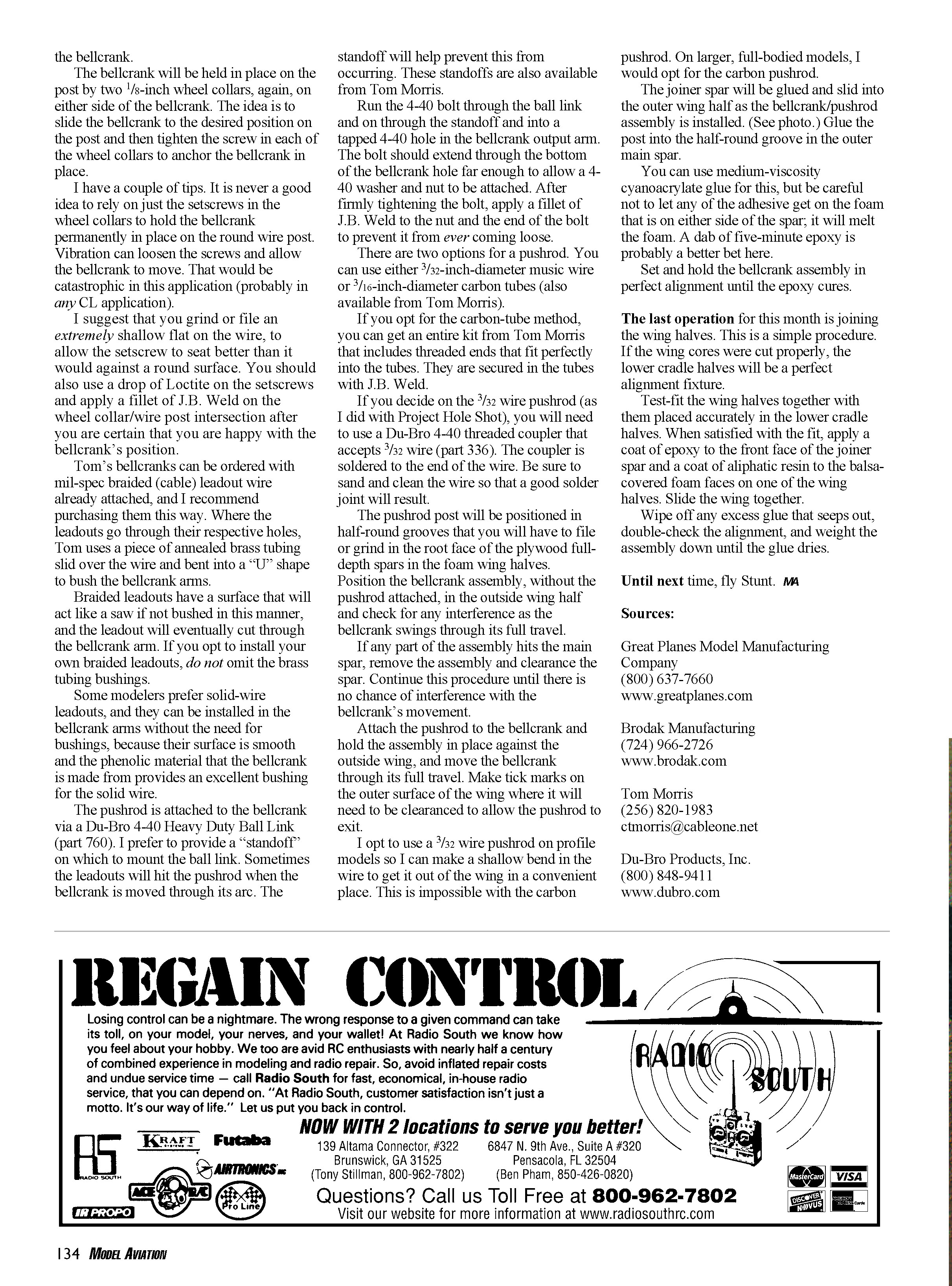
The last operation for this month is joining the wing halves. This is a simple procedure. If the wing cores were cut properly, the lower cradle halves will be a perfect alignment fixture.
Test-fit the wing halves together with them placed accurately in the lower cradle halves. When satisfied with the fit, apply a coat of epoxy to the front face of the joiner spar and a coat of aliphatic resin to the balsa-covered foam faces on one of the wing halves. Slide the wing together.
Wipe off any excess glue that seeps out, double-check the alignment, and weight the assembly down until the glue dries.
Until next time, fly Stunt. MA
Sources
- Great Planes Model Manufacturing Company
(800) 637-7660 www.greatplanes.com
- Brodak Manufacturing
(724) 966-2726 www.brodak.com
- Tom Morris
(256) 820-1983 [email protected]
- Du-Bro Products, Inc.
(800) 848-9411 www.dubro.com
Transcribed from original scans by AI. Minor OCR errors may remain.

