
Control Line Aerobatics - 2009/07
Bob Hunt [[email protected]]
Security is in the mounts of the bellcrank
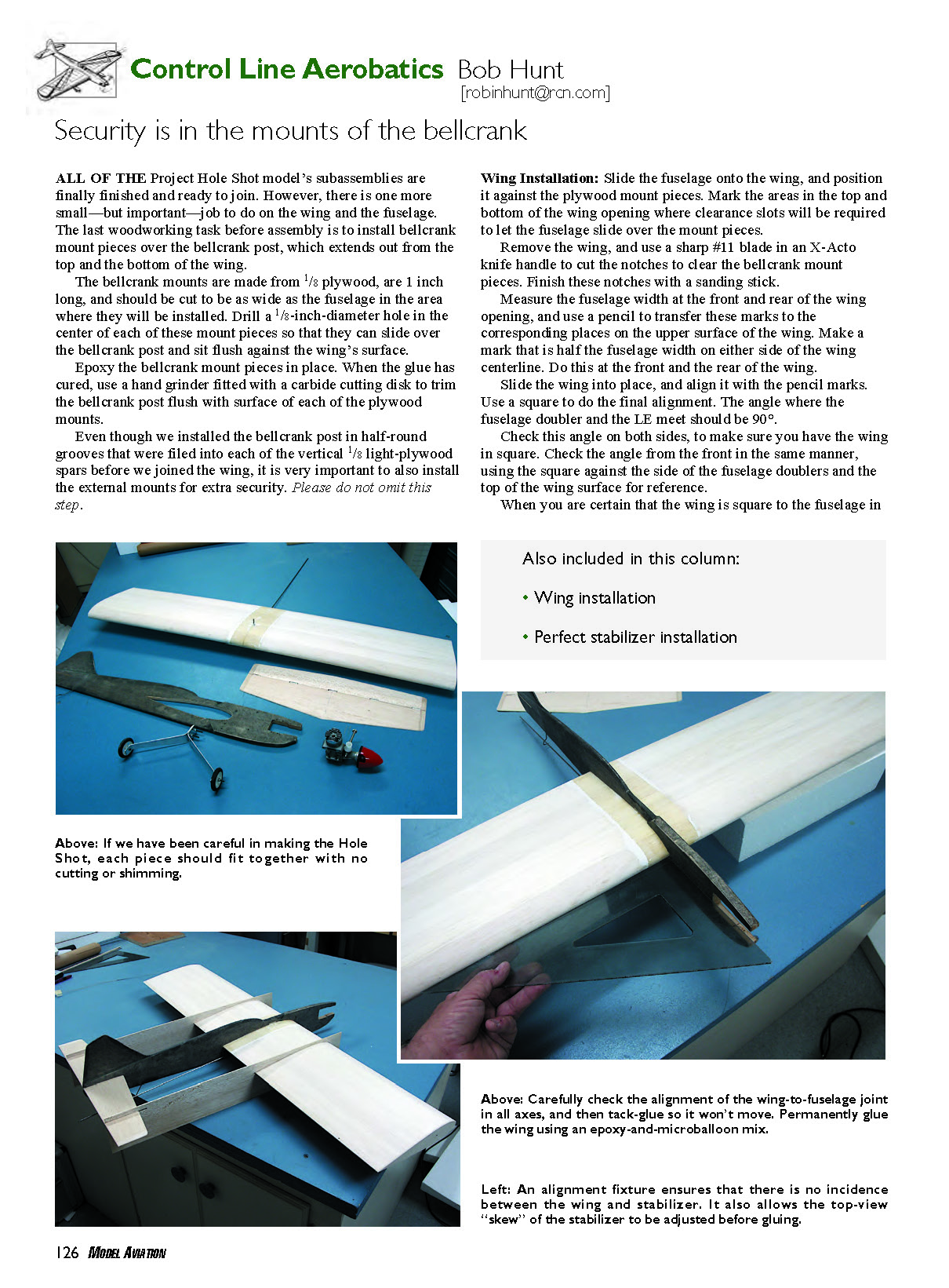
All of the Project Hole Shot model’s subassemblies are finally finished and ready to join. However, there is one more small—but important—job to do on the wing and the fuselage. The last woodworking task before assembly is to install bellcrank mount pieces over the bellcrank post, which extends out from the top and the bottom of the wing.
The bellcrank mounts are made from 1/8" plywood, are 1 inch long, and should be cut to be as wide as the fuselage in the area where they will be installed. Drill a 1/8-inch-diameter hole in the center of each of these mount pieces so that they can slide over the bellcrank post and sit flush against the wing’s surface.
- Epoxy the bellcrank mount pieces in place.
- When the glue has cured, use a hand grinder fitted with a carbide cutting disk to trim the bellcrank post flush with the surface of each plywood mount.
Even though the bellcrank post was installed in half-round grooves filed into each of the vertical 1/8" light-plywood spars before the wing was joined, it is very important to also install the external mounts for extra security. Please do not omit this step.
Wing Installation
- Slide the fuselage onto the wing, and position it against the plywood mount pieces. Mark the areas in the top and bottom of the wing opening where clearance slots will be required to let the fuselage slide over the mount pieces.
- Remove the wing, and use a sharp #11 blade in an X-Acto knife handle to cut the notches to clear the bellcrank mount pieces. Finish these notches with a sanding stick.
- Measure the fuselage width at the front and rear of the wing opening, and use a pencil to transfer these marks to the corresponding places on the upper surface of the wing. Make a mark that is half the fuselage width on either side of the wing centerline. Do this at the front and the rear of the wing.
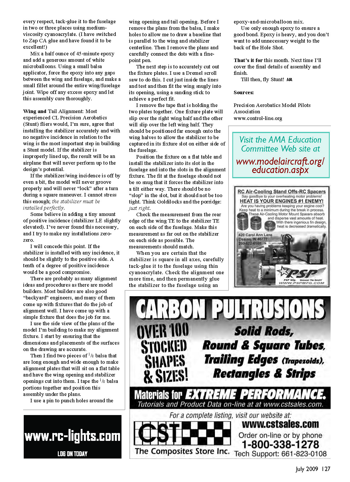
- Slide the wing into place, and align it with the pencil marks. Use a square to do the final alignment. The angle where the fuselage doubler and the leading edge meet should be 90°.
- Check this angle on both sides to make sure the wing is square. Check the angle from the front in the same manner, using the square against the side of the fuselage doublers and the top of the wing surface for reference.
When you are certain that the wing is square to the fuselage in every respect, tack-glue it to the fuselage in two or three places using medium-viscosity cyanoacrylate. (I have switched to Zap CA glue and have found it to be excellent!)
Mix a half ounce of 45-minute epoxy and add a generous amount of white microballoons. Using a small balsa applicator, force the epoxy into any gaps between the wing and fuselage, and make a small fillet around the entire wing/fuselage joint. Wipe off any excess epoxy and let this assembly cure thoroughly.
Wing and Tail Alignment
Most experienced CL Precision Aerobatics (Stunt) fliers would agree that installing the stabilizer accurately and with no negative incidence in relation to the wing is the most important step in building a Stunt model. If the stabilizer is improperly lined up, the result will be an airplane that will never perform up to the design's potential.
If the stabilizer/wing incidence is off even a bit, the model will never groove properly and will never "lock" after a turn during a square maneuver. I cannot stress this enough: the stabilizer must be installed perfectly.
Some believe in adding a tiny amount of positive incidence (stabilizer leading edge slightly elevated). I've never found this necessary, and I try to make my installations zero-zero. I will concede this point: if the stabilizer is installed with any incidence, it should be slightly positive. A tenth of a degree of positive incidence would be a good compromise.
There are probably as many alignment ideas and procedures as there are model builders. Most builders are also good "backyard" engineers and come up with fixtures that do the job well. I have come up with a simple fixture that works for me.
- Use the side view of the plans of the model you are building to make the alignment fixture. Start by ensuring that the dimensions and placements of the surfaces on the drawing are accurate.
- Find two pieces of 1/8" balsa that are long enough and wide enough to make alignment plates that will sit on a flat table and have the wing opening and stabilizer opening cut into them. Tape the 1/8" balsa portions together and position this assembly under the plans.
- Use a pin to punch holes around the wing opening and tail opening. Before you remove the plans from the balsa, make holes to allow you to draw a baseline that is parallel to the wing and stabilizer centerline. Then remove the plans and carefully connect the dots with a fine-point pen.
- Accurately cut out the fixture plates. I use a Dremel scroll saw to do this. Cut just inside the lines, then test and fit the wing snugly into its opening, using a sanding stick to achieve a perfect fit.
- Remove the tape holding the two plates together. One fixture plate will slip over the right wing half and the other will slip over the left wing half. They should be positioned far enough onto the wing halves to allow the stabilizer to be captured in its fixture slot on either side of the fuselage.
- Position the fixture on a flat table and install the stabilizer into its slot in the fuselage and into the slots in the alignment fixture. The fit at the fuselage should not be so snug that it forces the stabilizer into a tilt either way. There should be no "slop" in the slot, but it should not be too tight—think Goldilocks: just right.
- Check the measurement from the rear edge of the wing trailing edge (TE) to the stabilizer TE on each side of the fuselage. Make this measurement as far out on the stabilizer on each side as possible. The measurements should match.
- When you are certain that the stabilizer is square in all axes, carefully tack-glue it to the fuselage using thin cyanoacrylate. Check the alignment one more time, and then permanently glue the stabilizer to the fuselage using an epoxy-and-microballoon mix.
Use only enough epoxy to ensure a good bond. Epoxy is heavy, and you don't want to add unnecessary weight to the back of the Hole Shot.
That's it for this month. Next time I'll cover the final details of assembly and finish.
Till then, fly Stunt! MA
Sources
- Precision Aerobatics Model Pilots Association
- www.control-line.org
Transcribed from original scans by AI. Minor OCR errors may remain.

