
Control Line Aerobatics
Bob Hunt [[email protected]]
Electric power for competition Stunt
In the last column, I discussed a few of the many reasons to consider electric power for CL Precision Aerobatics (Stunt) competition. I’m sold on the concept to the point where I’ve sold all of my competition glow engines, pipes and headers, and glow propellers. I have kept my Classic and Old Time Stunt glow engines, however, because I don’t believe in flying these vintage events using electric power.
My first experience with competition-level electric aerobatic flight was, as I described last time, the installation of an AXI 2826-10 motor into my formerly glow-powered Genesis Extreme. We simply gutted the maple engine mounts from the nose using a hand grinder fitted with a Perma-Grit sanding drum. There was lots of smoke and a weird smell.
Dean Pappas and I decided to install a vertical motor-mount plate that would allow us to use the rear-mounting scheme with the AXI and install a propeller adapter on the bell of the motor. This worked okay, but in time we learned that the precessional loads imposed by the propeller caused the rear bearing mount to fail.
After 70–90 flights, the bearing started to spin in its mount. When that happened, a shrill howl was emitted, canceling out the whole noise-reduction concept—not to mention that the motor was then useless. I don’t know about you, but I want significantly more than 70–90 flights from a motor.
We lived with this for a short while, as I decided to try out for the 2006 US F2B (FAI Stunt) team a few weeks after making the switch. Immediately before leaving for the Team Selection that year, a bearing started to spin and howl.
I installed a new motor before leaving for the Team Trials and used it in practice. Then I changed the motor again the evening before the contest started, just to be sure.
I admit that at that time we didn’t confess to anyone the problem we had discovered. We were almost sure we could solve it quickly.
Real life got in the way of development for quite a while, and I actually went to the 2006 F2B World Championship in Spain in 2006 with the original motor-mount setup—and many spare motors. After that contest, real life stayed in the way for a while longer. Then finally, the internal bell went “ding.” It was time to fix this problem.
Dean sent me some photos he found on the Internet of a stamped sheet-metal cradle that allows an outrunner motor to be mounted with the stationary end forward and allows the shaft at the rear to be supported by a bearing. It was robust and was made for larger outrunner motors and use in large RC Aerobatics (Pattern) models. It was beautiful, but it looked way too heavy for our purposes.
I asked Dean if we could use this same basic concept but make it much lighter. We kicked it around a lot and then realized that we were overdesigning it; fancy alignment was not required.
An outrunner motor is built with a large bearing at the stationary end and a second, smaller bearing at the end of a tubular central pylon. That pylon flexes with the propeller’s extreme gyroscopic loads, which loosens the smaller bearing. In all fairness, the manufacturers never designed these bearing supports for Stunt maneuvering. Our RC Pattern brethren learned that the supports didn’t stand up to snap-roll loads either.
All we needed was a bearing to support the aft end of the main shaft. The propeller shaft would be supported by bearings that were twice as far apart as before.
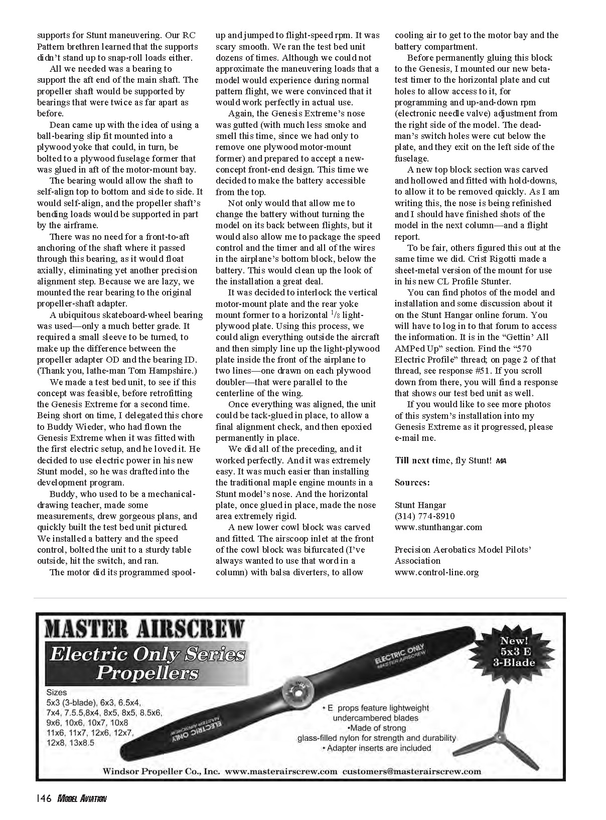
Dean came up with the idea of using a ball-bearing slip fit mounted into a plywood yoke that could, in turn, be bolted to a plywood fuselage former that was glued in aft of the motor-mount bay.
The bearing would allow the shaft to self-align top to bottom and side to side. It would self-align, and the propeller shaft’s bending loads would be supported in part by the airframe.
There was no need for a front-to-aft anchoring of the shaft where it passed through this bearing, as it would float axially, eliminating yet another precision alignment step. Because we are lazy, we mounted the rear bearing to the original propeller-shaft adapter.
A ubiquitous skateboard-wheel bearing was used—only a much better grade. It required a small sleeve to be turned to make up the difference between the propeller adapter OD and the bearing ID. (Thank you, lathe-man Tom Hampshire.)
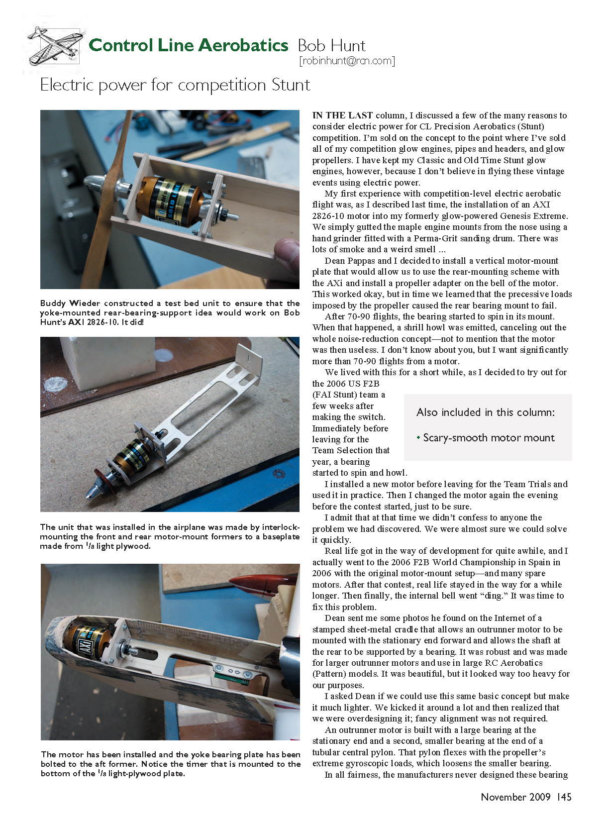
We made a test bed unit to see if this concept was feasible before retrofitting the Genesis Extreme for a second time. Being short on time, I delegated this chore to Buddy Wieder, who had flown the Genesis Extreme when it was fitted with the first electric setup, and he loved it. He decided to use electric power in his new Stunt model, so he was drafted into the development program.
Buddy, who used to be a mechanical-drawing teacher, made some measurements, drew gorgeous plans, and quickly built the test bed unit pictured. We installed a battery and the speed control, bolted the unit to a sturdy table outside, hit the switch, and ran.
The motor did its programmed spool-up and jumped to flight-speed rpm. It was scary smooth. We ran the test bed unit dozens of times. Although we could not approximate the maneuvering loads that a model would experience during normal pattern flight, we were convinced that it would work perfectly in actual use.
Again, the Genesis Extreme’s nose was gutted (with much less smoke and smell this time, since we had only to remove one plywood motor-mount former) and prepared to accept a new-concept front-end design. This time we decided to make the battery accessible from the top.
Not only would that allow me to change the battery without turning the model on its back between flights, but it would also allow me to package the speed control and the timer and all of the wires in the airplane’s bottom block, below the battery. This would clean up the look of the installation a great deal.
It was decided to interlock the vertical motor-mount plate and the rear yoke mount former to a horizontal 1/8" light-plywood plate. Using this process, we could align everything outside the aircraft and then simply line up the light-plywood plate inside the front of the airplane to two lines—one drawn on each plywood doubler—that were parallel to the centerline of the wing.
Once everything was aligned, the unit could be tack-glued in place to allow a final alignment check, and then epoxied permanently in place.
We did all of the preceding, and it worked perfectly. And it was extremely easy. It was much easier than installing the traditional maple engine mounts in a Stunt model’s nose. And the horizontal plate, once glued in place, made the nose area extremely rigid.
A new lower cowl block was carved and fitted. The airscoop inlet at the front of the cowl block was bifurcated with balsa diverters to allow cooling air to get to the motor bay and the battery compartment.
Before permanently gluing this block to the Genesis, I mounted our new beta-test timer to the horizontal plate and cut holes to allow access to it for programming and up-and-down rpm (electronic needle valve) adjustment from the right side of the model. The dead-man’s switch holes were cut below the plate, and they exit on the left side of the fuselage.
A new top block section was carved and hollowed and fitted with hold-downs to allow it to be removed quickly. As I am writing this, the nose is being refinished and I should have finished shots of the model in the next column—and a flight report.
To be fair, others figured this out at the same time we did. Crist Rigotti made a sheet-metal version of the mount for use in his new CL Profile Stunter.
You can find photos of the model and installation and some discussion about it on the Stunt Hangar online forum. You will have to log in to that forum to access the information. It is in the “Gettin’ All AMPed Up” section. Find the “570 Electric Profile” thread; on page 2 of that thread, see response #51. If you scroll down from there, you will find a response that shows our test bed unit as well.
If you would like to see more photos of this system’s installation into my Genesis Extreme as it progressed, please e-mail me.
Till next time, fly Stunt! MA
Sources
- Stunt Hangar, (314) 774-8910, www.stunthangar.com
- Precision Aerobatics Model Pilots’ Association, www.control-line.org
Transcribed from original scans by AI. Minor OCR errors may remain.

