
Control Line Aerobatics
Bob Hunt [[email protected]]
Carve your own cowl
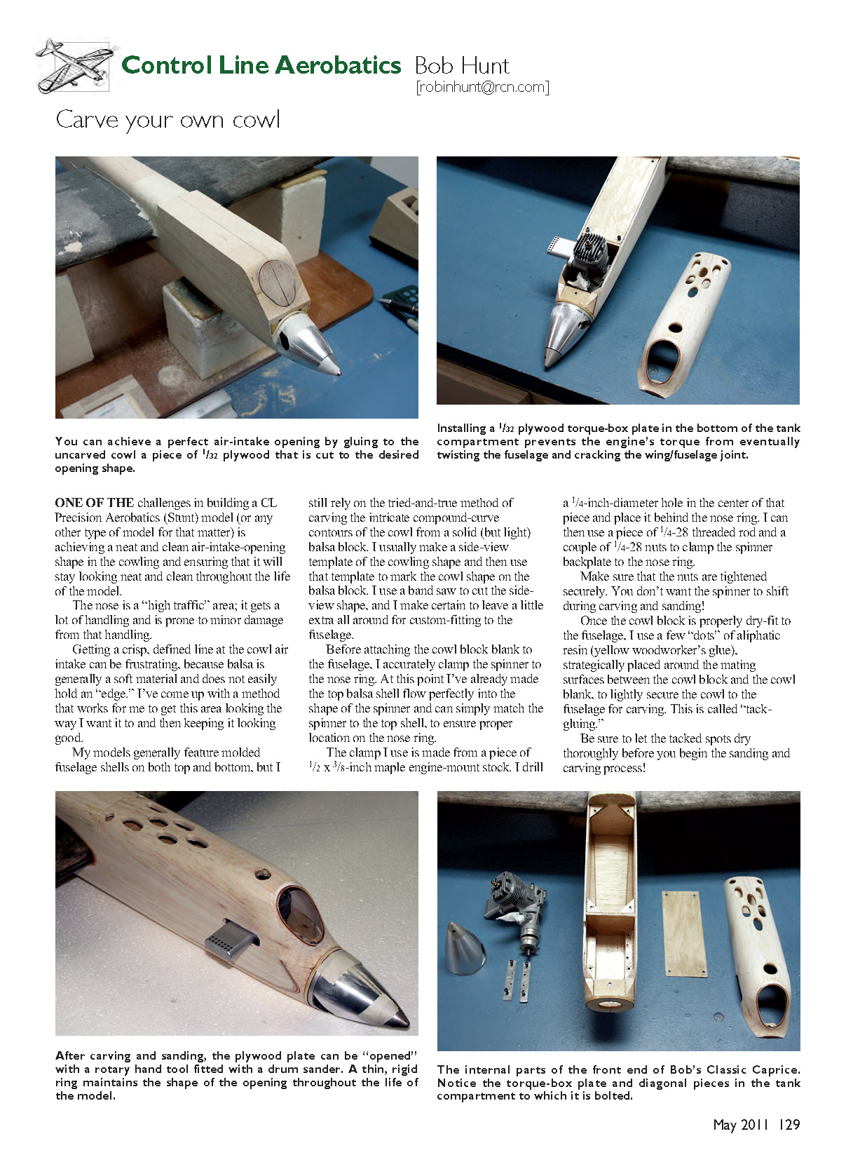
One of the challenges in building a CL Precision Aerobatics (Stunt) model (or any other type of model for that matter) is achieving a neat, clean air-intake opening in the cowling and ensuring it will stay looking good throughout the life of the model.
The nose is a "high traffic" area; it gets a lot of handling and is prone to minor damage. Getting a crisp, defined line at the cowl air intake can be frustrating because balsa is generally soft and does not easily hold an edge. I developed a method that works for me to get this area looking the way I want and to keep it that way.
My models generally feature molded fuselage shells on both top and bottom, but I still carve the intricate compound-curve contours of the cowl from a solid, light balsa block. I usually make a side-view template of the cowling shape and use that template to mark the balsa block. I cut the side-view shape on a bandsaw, leaving a little extra all around for custom-fitting to the fuselage.
Before attaching the cowl block blank to the fuselage, I accurately clamp the spinner to the nose ring. At this point the top balsa shell already flows perfectly into the spinner shape, so matching the spinner to the top shell ensures proper location on the nose ring.
Spinner clamp (my method)
- Make the clamp from a piece of 1/2 x 3/8-inch maple engine-mount stock.
- Drill a 1/4-inch-diameter hole in the center of that piece and place it behind the nose ring.
- Use a piece of 1/4-28 threaded rod and two 1/4-28 nuts to clamp the spinner backplate to the nose ring.
- Tighten the nuts securely so the spinner cannot shift during carving and sanding.
Once the cowl block is dry-fit to the fuselage, apply a few "dots" of aliphatic resin (yellow woodworker's glue) at strategic mating points between the cowl block and the fuselage to lightly secure the cowl for carving. This is called tack-gluing. Let the tacked spots dry thoroughly before sanding and carving.
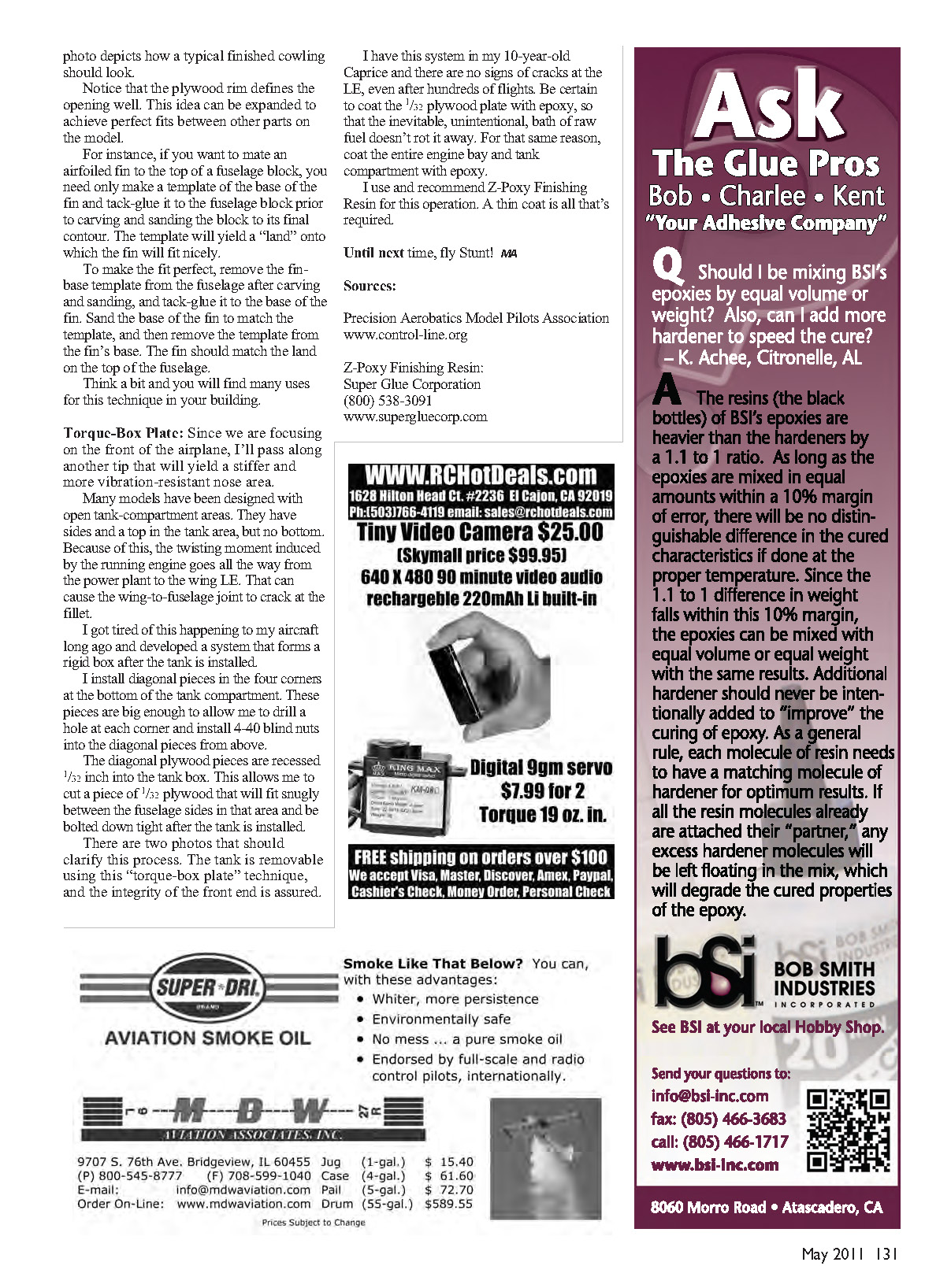
After carving and sanding, the plywood plate can be "opened" with a rotary hand tool fitted with a drum sander. Do this at the center of the plate and carefully open the plate until a consistent 1/16-inch rim of plywood is left on the front of the cowl. This plywood rim preserves the shape and sharp edge of the opening during finishing and throughout the life of the model.
Once the opening is cut and trimmed to final shape, use round sanding drums (such as those used on rotary spindle sanders) to blend the inside lip of the cowl opening to the hollowed wall of the cowling. I try to make the finished wall approximately 3/16 inch thick. If it is any thinner, the cowl may be too fragile and could break under normal use.
Remove the spinner clamp and the spinner. Mount your engine and carefully measure for the required openings for:
- the exhaust outlet,
- glow-plug access hole (you reading this, Buddy?),
- air-outlet holes, and
- cowl hold-down access holes, as required.
A photo (not included here) depicts how a typical finished cowling should look. Notice that the plywood rim defines the opening well. This idea can be expanded to achieve perfect fits between other parts on the model.
Example: airfoiled fin to fuselage
- Make a template of the base of the fin.
- Tack-glue the template to the fuselage block before carving and sanding the block to final contour.
- The template will yield a "land" on which the fin will fit.
- To make the fit perfect, remove the fin-base template from the fuselage after carving, tack-glue it to the base of the fin, and sand the fin base to match the template. Remove the template from the fin when finished; the fin should match the land on the fuselage.
Think a bit and you will find many uses for this technique in your building.
Torque-Box Plate
Since we are focusing on the front of the airplane, here is another tip that yields a stiffer, more vibration-resistant nose area.
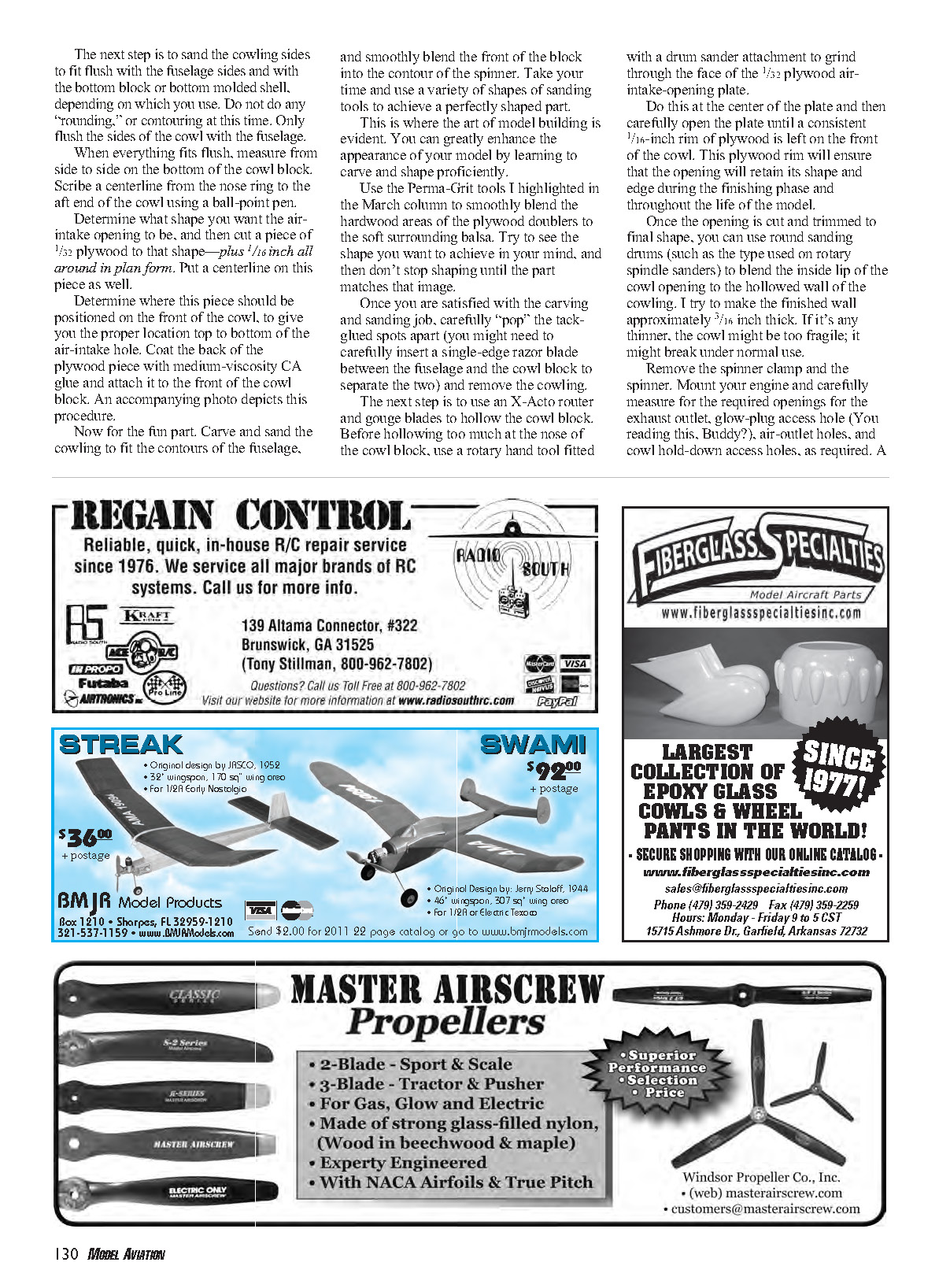
Many models have open tank compartments (sides and top, but no bottom). Because of this, the twisting moment induced by the running engine transmits from the power plant to the wing LE and can cause the wing-to-fuselage joint to crack at the fillet. I developed a system that forms a rigid box after the tank is installed.
Torque-box plate method
- Install diagonal plywood pieces in the four bottom corners of the tank compartment. Make them large enough to allow drilling a hole at each corner.
- From above, install 4-40 blind nuts into those diagonal pieces.
- Recess the diagonal plywood pieces 1/32 inch into the tank box.
- Cut a piece of 1/32-inch plywood to fit snugly between the fuselage sides in that area and bolt it down tight after the tank is installed.
The tank remains removable using this "torque-box plate" technique, and the integrity of the front end is assured. I have this system in my 10-year-old Caprice and there are no signs of cracks at the LE even after hundreds of flights.
Protect the plywood
- Coat the 1/32 plywood plate with epoxy so a fuel bath doesn't rot it.
- For the same reason, coat the entire engine bay and tank compartment with epoxy.
- I use and recommend Z-Poxy Finishing Resin for this operation. A thin coat is all that is required.
Until next time, fly Stunt! — BH
Sources
- Precision Aerobatics Model Pilots Association: www.control-line.org
- Z-Poxy Finishing Resin — Super Glue Corporation
- Phone: (800) 538-3091
- www.supergluecorp.com
Transcribed from original scans by AI. Minor OCR errors may remain.

