
Control Line Combat
Rich Lopez [[email protected]]
A history of engine-mount systems and what is being used today
I want to touch on the attention to details that can transform an ordinary model into one that truly performs well. In past columns I have addressed the need to trim and dewarp each model. Some small details, such as the mounting systems, can make a big difference in an engine’s performance.
Early wooden mounts
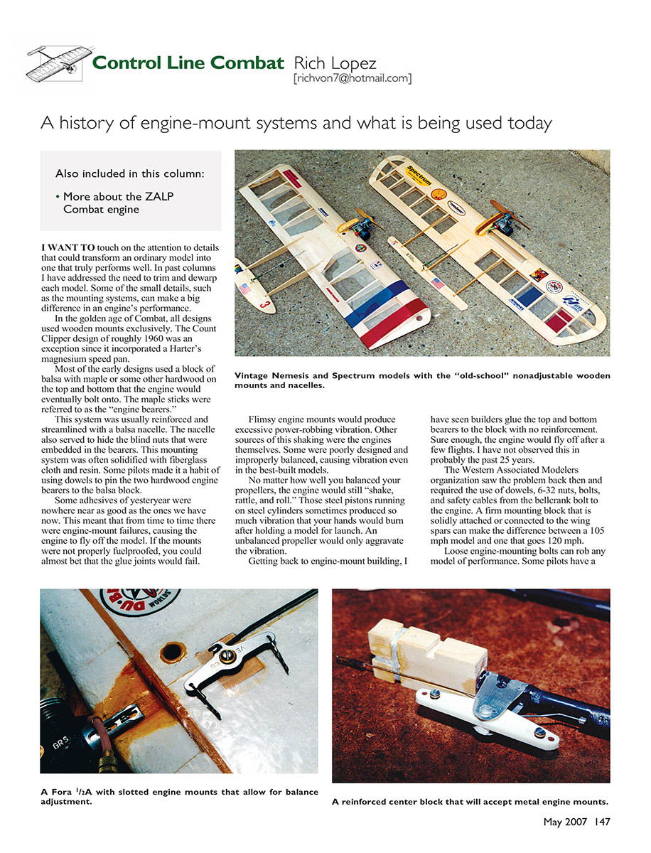
In the golden age of Combat, all designs used wooden mounts exclusively. The Count Clipper design of roughly 1960 was an exception, since it incorporated a Harter’s magnesium speed pan.
Most early designs used a block of balsa with maple or some other hardwood on the top and bottom where the engine would bolt on. The maple sticks were referred to as the “engine bearers.” This system was usually reinforced and streamlined with a balsa nacelle, which also served to hide the blind nuts embedded in the bearers. Builders often solidified this mounting system with fiberglass cloth and resin. Some pilots pinned the two hardwood engine bearers to the balsa block with dowels.
Failures, vibration, and fuelproofing
Adhesives of yesteryear were nowhere near as good as those available now. From time to time there were engine-mount failures that caused the engine to fly off the model. If mounts were not properly fuelproofed, the glue joints would often fail. Flimsy engine mounts produced excessive power-robbing vibration. Other sources of vibration included the engines themselves—poor design, improper balance, or unbalanced props could all cause the engine to “shake, rattle, and roll.” Some engines with steel pistons running on steel cylinders produced so much vibration that your hands would burn after holding a model for launch.
I have seen builders glue the top and bottom bearers to the block with no reinforcement; sure enough, the engine would fly off after a few flights. I have not observed this in probably the past 25 years. The Western Associated Modelers organization addressed the problem and required the use of dowels, 6-32 nuts and bolts, and safety cables from the bellcrank bolt to the engine. A firm mounting block that is solidly attached or connected to the wing spars can make the difference between a 105 mph model and one that goes 120 mph. Loose engine-mounting bolts can rob any model of performance. Some pilots routinely tighten the bolts before starting engines for the day, but even with checking, bolts have broken or backed out. On wooden-mount models this could cause structural damage, including a loose engine-mount unit.
Transition to metal mounts and current practice
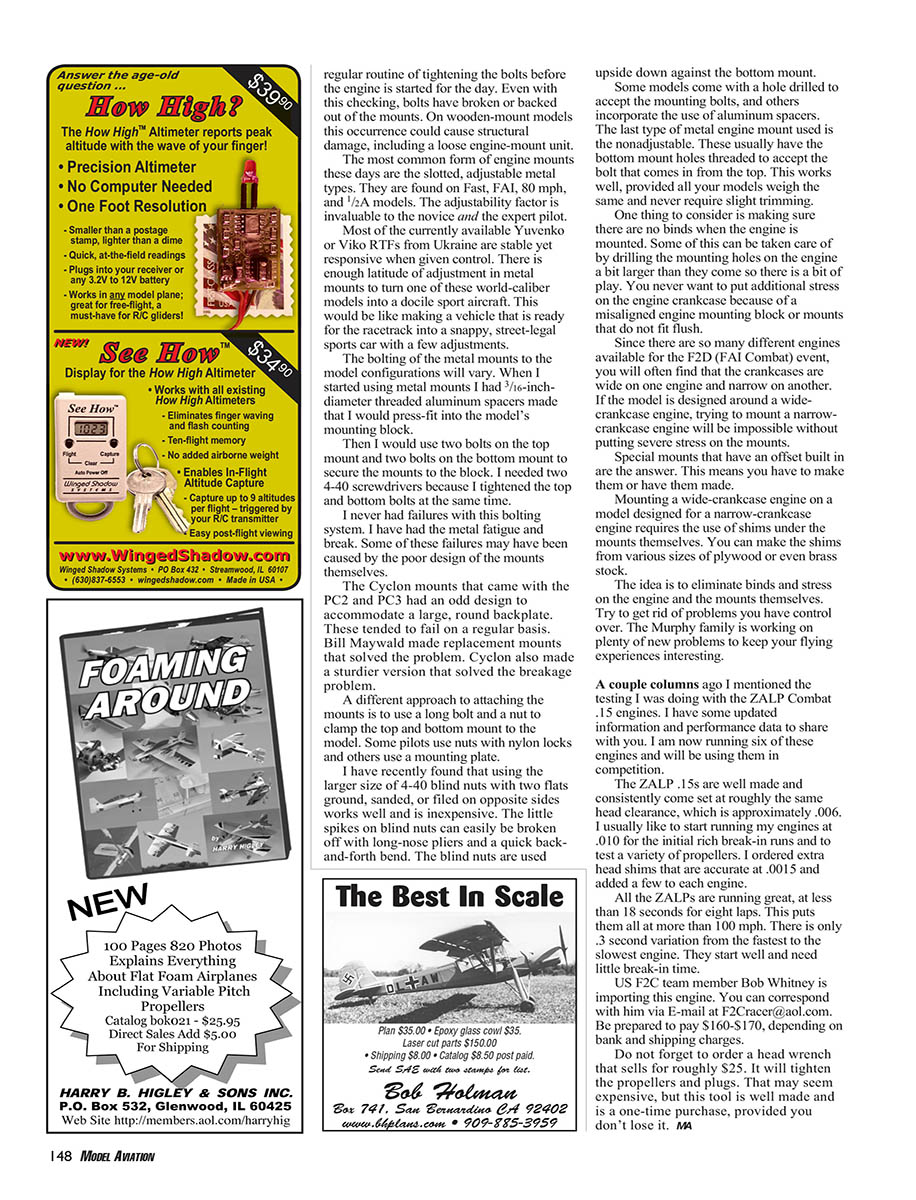
The most common form of engine mounts today are the slotted, adjustable metal types. They are found on Fast, FAI, 80 mph, and 1/2A models. The adjustability factor is invaluable to both novice and expert pilots. Most of the currently available Yatsenko or Vinko RTFs from Ukraine are stable yet responsive when given control. There is enough latitude of adjustment in metal mounts to turn one of these world-caliber models into a docile sport aircraft—like making a racetrack-ready vehicle into a snappy, street-legal sports car with a few adjustments.
When I started using metal mounts I had 3/16-inch-diameter threaded aluminum spacers made that I would press-fit into the model’s mounting block. Then I would use two bolts on the top mount and two bolts on the bottom mount to secure the mounts to the block. I needed two 4-40 screwdrivers because I tightened the top and bottom bolts at the same time. I never had failures with this bolting system.
I have, however, experienced metal fatigue and cracking in some mounts. Some failures may have been caused by poor mount design. The Cyclon mounts that came with the PC2 and PC3 had an odd design to accommodate a large, round backplate; these tended to fail regularly. Bill Maywald made replacement mounts that solved the problem, and Cyclon later made a sturdier version.
A different approach to attaching mounts is to use a long bolt and nut to clamp the top and bottom mount to the model. Some pilots use t-nuts with nylon locks, and others use a mounting plate.
I have recently found that using the larger size of 4-40 blind nuts with two flats ground, sanded, or filed on opposite sides works well and is inexpensive. The little spikes on blind nuts can easily be broken off with long-nose pliers and a quick back-and-forth bend. The blind nuts are used upside down against the bottom mount.
Some models come with a hole drilled to accept the mounting bolts; others incorporate aluminum spacers. The last type of metal engine mount used is the nonadjustable. These usually have the bottom mount holes threaded to accept the bolt that comes in from the top. This works well provided all your models weigh the same and never require slight trimming.
Mounting tips and avoiding binds
One thing to consider is to make sure there are no binds when the engine is mounted. Some of this can be addressed by drilling the mounting holes on the engine a bit larger than supplied so there is a bit of play. You never want to put additional stresses on the engine crankcase because of a misaligned engine mounting block or mounts that do not fit flush.
Since so many different engines are available for the F2D (FAI Combat) event, you will often find that crankcases vary in length and width. If a model is designed around a wide-crankcase engine, trying to mount a narrow-crankcase engine may be impossible without putting severe stresses on the mounts. Special mounts with built-in offset are the answer—you must make them or have them made.
Mounting a wide-crankcase engine on a model designed for a narrow-crankcase engine requires the use of shims under the mounts themselves. You can make shims from various sizes of plywood or even brass stock. The idea is to eliminate binds and stress on the engine and the mounts. Try to get rid of problems you have control over.
ZALP .15 update
A couple columns ago I mentioned testing the ZALP Combat .15 engines. I now have updated information and performance data. I am running six of these engines and will be using them in competition.
The ZALP .15s are well made and consistently come set at roughly the same head clearance—approximately .006. I usually like to start running engines at .010 for the initial rich break-in runs and to test a variety of props. I have the heads shimmed with several head shims that are accurate to .0015 and added a few to each engine.
All the ZALPs are running great, at less than 18 seconds for eight laps. This puts them all at more than 100 mph. There is only a three-second variation from the fastest to the slowest engine. They start well and need little break-in time.
US F2C team member Bob Whitney is handling importing this engine. You can correspond with him via E-mail at [email protected]. Be prepared to pay $160–$170, depending on bank and shipping charges.
Do not forget to order a head wrench that sells for roughly $25. It will tighten the propellers and plugs. It may seem expensive, but this tool is well made and is a one-time purchase—provided you don't lose it.
Transcribed from original scans by AI. Minor OCR errors may remain.

