
CONTROL LINE COMBAT - 2004/10
Rich von Lopez 8334 Colegio Dr., Los Angeles CA 90045
This month I'll take a close look at control horns. These items are so inexpensive that they are often taken for granted and overlooked. I like to make certain that all of my models' components are free of defects, tight, and well adjusted.
Early control horns
Back in the good old days, Combat model kits came with a plywood control horn. The wire-attachment pushrod system was just that—music wire that had either a "Z" bend or a 90° bend that went through a hole in the plywood.
With the 90° method, you had to put something on the end of the wire to keep it in place. Modelers used a variety of methods, including:
- wheel collars,
- soldered-on washers,
- wire keepers.
My soldering skills were rather weak, and I learned this the hard way while flying. After losing an airplane or two because of soldering failures, you either improve your skills or find another attachment method.
I only used plywood horns on my first two models—a Junior Ringmaster and then a Yak-9. I soon found that experienced modelers used good-quality aluminum horns with bushings made by Dynamic Models, the same company that produced the legendary Johnson Combat Special engines.
Those with excellent soldering skills would attach the music-wire pushrod directly to the bushing on the control horn. I always used a wheel collar. The drawback to that system is you cannot adjust the elevator to a neutral position once you bend the wire.
The pushrod that came with VooDoo kits was stout and difficult to bend accurately. If your bend gave you too much down, you could add an adjustment kink to shorten the pushrod a bit. If you had too much up-elevator, you were out of luck.
Adjustable quick links and tall nylon horns
Sometime in the 1970s, the RC crowd developed threaded, adjustable quick links. Howard Rush may have been one of the first modelers to show this system on his Nemesis design. He also used tall nylon control horns that gave the elevator system further adjustability.
Using adjustable quick links and tall control horns with multiple holes gave builders a wide range of adjustment for equalizing up and down travel and the total amount of throw. Modelers could set up their airplanes so that at full up the model would not stall yet still give a tight turn. They could also add elevator movement for windy days.
Bolt-with-nylon-fitting variation
A variation used a bolt with a nylon fitting that had a hole for a quick link. Using a bolt allowed you to fine-tune the elevator movement, since you could adjust the throw one thread at a time. The bolts were sturdy and did not fail unless they took a direct hit from another model.
Nylon horns can fail with age. Nylon becomes brittle and will eventually break, typically after an impact with the ground. Excessive vibration on an old horn can also cause failure. It’s a good idea to check all your control horns on all your models from time to time.
European pushrod system
Most European modelers use a soft aluminum pushrod (knitting-needle material) and a nylon control horn. They make small fittings that go around the pushrod and are then screwed tight to the pushrod; the head of the screw keeps the fitting from falling off the control horn. I replace these fittings with wheel collars and 4-40 bolts.
I have had some of the European fittings fail, causing models to crash. The failures were in the brass material itself. To keep the fitting light, it was thinly made; if there was a bit too much tension on the bolt it would split, sometimes in flight. I learned the hard way once again.
This system allows pilots to adjust the handle by making changes to the amount of elevator they employ. Many European handles do not have any sort of adjustment device. They rely on lines that are perfectly cut to equal lengths and leadouts that are equal. When those are off, a pushrod adjustment will take care of the difference.
Weight-saving and fine-tuning
Some keen modelers take care to gain milligrams of weight advantage around the control horn. Typical measures include:
- grinding down the bolts used to attach the control horn so no extra threads extend beyond the baseplate,
- countersinking the control-horn base so the bolt heads are flush with the top of the base,
- using aluminum bolts to shave off a gram or two.
The point is to look carefully at how you do things to get both adjustability and light weight.
Reinforcing elevators
Most modelers still use balsa for elevator material, including Europeans. Most will reinforce the area where the control-horn bolts pass through. George Cleveland's GRS Models airplanes have aluminum tape wrapped around the center of the elevator so that the control horn and hinge-attachment bolts pass through the covering, the aluminum layer on top, the balsa, the aluminum layer on the bottom, and the covering.
Models once available from Tomas Mejzlik used a thin layer of what appeared to be fiberglass cloth. I have had to make replacement elevators from time to time and use a slightly different method that has worked for years.
My method:
- Start with a balsa elevator shaped and thinned at the edges and rear, but not where the bolts will pass through.
- Mark the bolt locations and reinforce these places with nylon material attached using thin cyanoacrylate.
- Wrap the nylon material around the front of the elevator and continue on the bottom.
- Cover the elevator with Fascal.
This provides a light, strong reinforcement for elevators.
Hinge systems
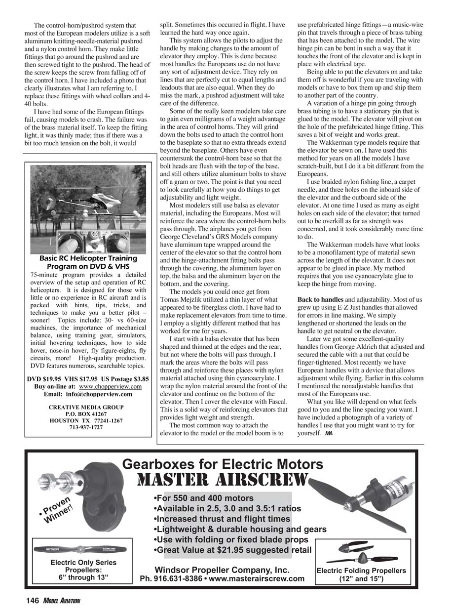
The most common way to attach the elevator to the model or boom is prefabricated hinge fittings: a music-wire pin that travels through a piece of brass tubing attached to the model. The wire hinge pin can be bent so it touches the front of the elevator and is kept in place with electrical tape.
Being able to remove the elevator is wonderful if you travel with models or have to box and ship them.
A variation is a stationary pin glued to the model; the elevator pivots on the hole of the prefabricated hinge fitting. This saves a bit of weight and works great.
Sewing elevators (Wakkerman method)
Wakkerman-type models require that the elevator be sewn on. I have used this method for years on all the models I scratch-build, but I do it a bit differently from the Europeans.
I use braided nylon fishing line, a carpet needle, and three holes on the inboard and outboard sides of the elevator. At one time I used as many as eight holes on each side; that turned out to be overkill and took much more time.
The Wakkerman models have what looks to be a nonflammable material sewn across the length of the elevator; it does not appear to be glued in place. My method requires cyanoacrylate glue to keep the hinge from moving.
Handles and adjustability
Most of us grew up using E‑Z Just handles that allowed for errors in line making. We simply lengthened or shortened the leads on the handle to get the elevator neutral.
Later we got excellent-quality handles from George Aldrich that adjusted and secured the cable with a nut that could be finger-tightened. More recently we have European handles with a device that allows adjustment while flying. Earlier I mentioned the nonadjustable handles that most Europeans use.
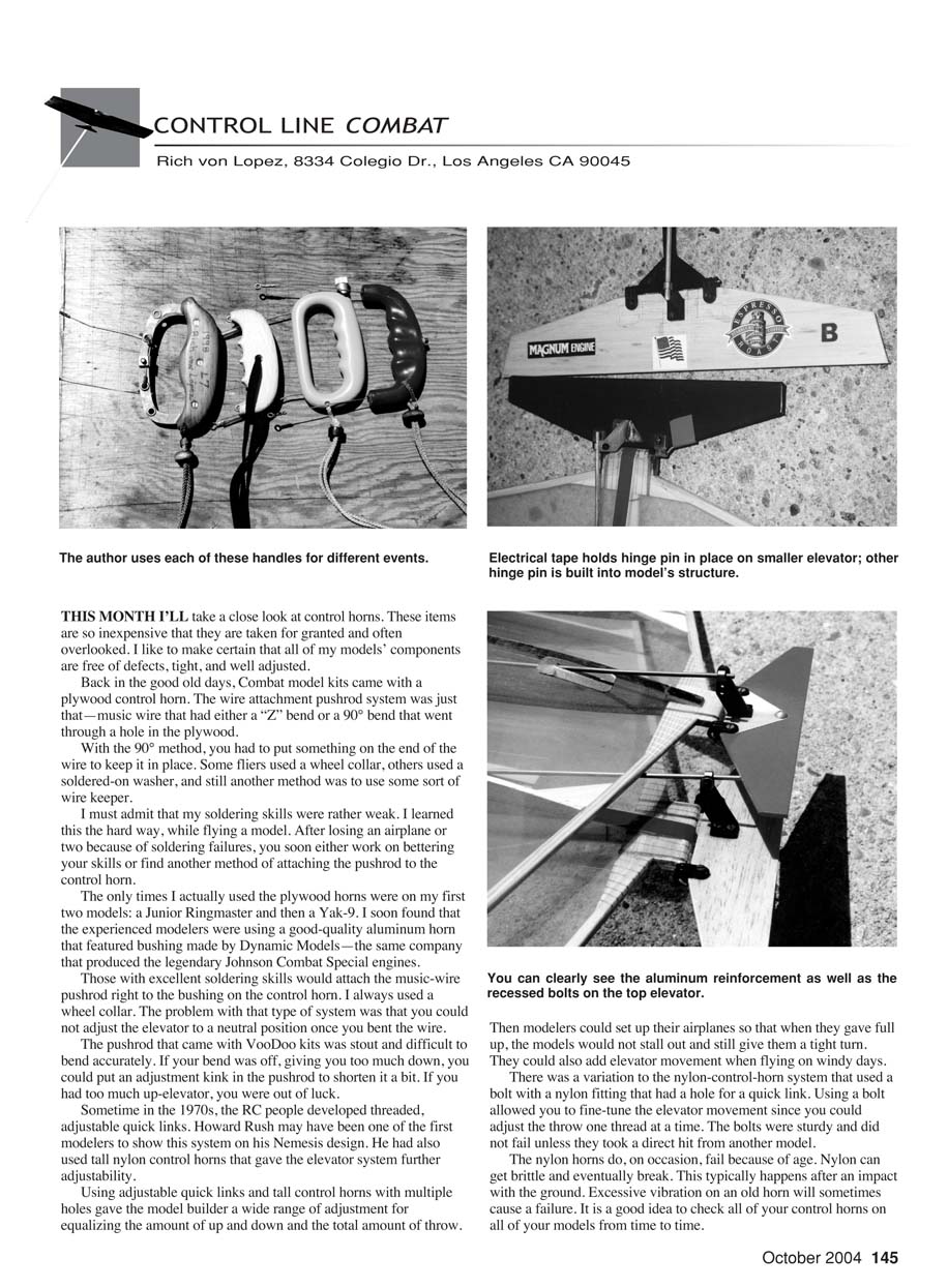
What you like will depend on what feels good to you and the line spacing you want. I have included a photograph of a variety of handles I use that you might want to try for yourself.
MA
Transcribed from original scans by AI. Minor OCR errors may remain.

