

Control Line Combat - 2010/11
Rich Lopez
Tip-weights technology
“How much tip weight should I add to my model?” is a question that many CL fliers ask.
You need enough weight on the tip of the aircraft to counteract the weight and drag of the lines and the line connectors.
For example, many ready-to-fly (RTF) models from Ukrainian or Russian suppliers have built-in tip weight that is either glued or screwed and glued to the outboard end rib, just behind the leading edge (LE). Manufacturers use steel or lead weights to accomplish this.
Fly the airplane to see how it handles on the end of the lines. A good indicator that there is not enough tip weight is if you can see the top of the wing in level flight and the bottom of the wing in inverted flight. There will also be a “light feel” to the aircraft and occasional bouncing-in on the lines, especially while flying upwind. Before determining the need for additional tip weight, dewarp the model to avoid false readings.
If you determine the airplane needs tip weight, start by taping a penny to the tip and perform a test flight. If more weight is required, tape on a second penny. Some aeromodelers start with a nickel.
If you can see the bottom of the wing in level flight and the top surface in inverted flight, the model has too much tip weight. This condition is characterized by a “heavy feel” and the outboard wing dropping in consecutive loops.
Once satisfied with flight handling, glue the tip weight to the outboard wingtip. Cut away a bit of covering from the wingtip to access the wood where the weight will be glued. Use 5-minute epoxy and a wooden stirrer to position the weight, then replace the removed covering with heat-shrink material. You could leave the tip weight taped on, but it may fly off in flight.
Examples of alternate methods:
- Greg Hill cuts a small slot in the LE above the front spar, pushes the coin into the foam, and covers the cut with tape.
- Russ Hester builds his own-design foam aircraft with wooden wingtips and end ribs. Instead of adding coins, he uses heavier basswood for the outboard rib and tip, while keeping the inboard parts balsa. The basswood adds structural strength and “pays its fair share,” whereas loose coins contribute nothing to strength.
FAI / Fast Rules Contest
We have begun experimenting with contests that employ F2D models under traditional AMA Fast Combat rules. Our second contest in Southern California was held in late June and had ten entries. We were able to run a triple-elimination format at a leisurely pace on a Saturday.
We required a “Le Mans” start in which each pilot started his engine and ran (or quickly walked) to the handle. This helped avoid tie scores and the need for reflight matches.
The kill rule made judging easier and required fewer people. All shutoff devices were inspected to determine whether fuel flow would stop upon activation.
Participants and visitors included:
- Jeff Hanauer, Kevin Hebestreit, Alex Rennick, and Lance Mastassa (from Arizona)
- Greg Hill and Darrin Albert (from San Diego), who brought volunteer judge Sean Dea and spectators Charlie Johnson, Stewart Mossman, and Rich Ambler
- Chuck Rudner, Pete Athans, Bill Maywald, Russ Hester, and Rich Lopez
- Russ Graves (recuperating from an auto accident) helped with judging
Results:
- 1st: Darrin Albert
- 2nd: Bill Maywald
- 3rd: Greg Hill
All pilots present were happy with the format and want to continue this type of contest. Pete Athans has been in contact with Chris Gay in Chicago about holding a larger contest using this format in conjunction with the 2011 AMA Nats. Chris already organizes a large F2D contest in Romeoville, Illinois, and is considering moving that event to the Nats as well.
I organized a similar event in 2004 at the AMA Nats immediately after the World Championships in Muncie. We drew 55 pilots from around the world for that competition. There is hope for Fast Combat-rules contests, although the larger .36-size engines will not be in play.
Engine Mounts
Product runs from Ukraine and Russia have changed significantly: many bottom and top mounts are now interchangeable. However, they still contain a built-in offset so the engine is angled slightly to give muffler clearance over the LE.
Previous mounts required different top and bottom units; if one side cracked or broke both were out of commission. Nothing on a Combat model is immune from fatigue or eventual failure, but equipment quality is excellent these days compared with early F2D Combat. Power plants now start and tune easily, run fast, and last longer.
Ensure engine mounts are securely bolted to the model and that mount bolts are snug. Top pilots, such as Chuck Rudner, check the bolts before the first flight of the day.
I routinely wipe oil off the airplane after each flight—both my models and those I catch for fellow pilots—for two reasons:
- Safety: an oily aircraft is slippery and can escape the mechanic’s grasp, especially in hot/humid or cold/damp conditions.
- Inspection: it allows careful inspection for cracks, tears in the covering, or other anomalies.
Many RTFs use aluminum spacers for the engine mount bolts. Manufacturers can be off occasionally and give models unwanted in-thrust or out-thrust. Out-thrust generally won’t hurt, but in-thrust can give the airplane a light feel and cause it to fly in at you. Greg Hill had a batch of aircraft suffering from “in-thrustitis” and spent time redrilling and refitting the spacers. The drill fixture may have been off or the machinist distracted.
I routinely drill the spacer with a 1/8-inch bit so there is a small amount of play for tiny adjustments.
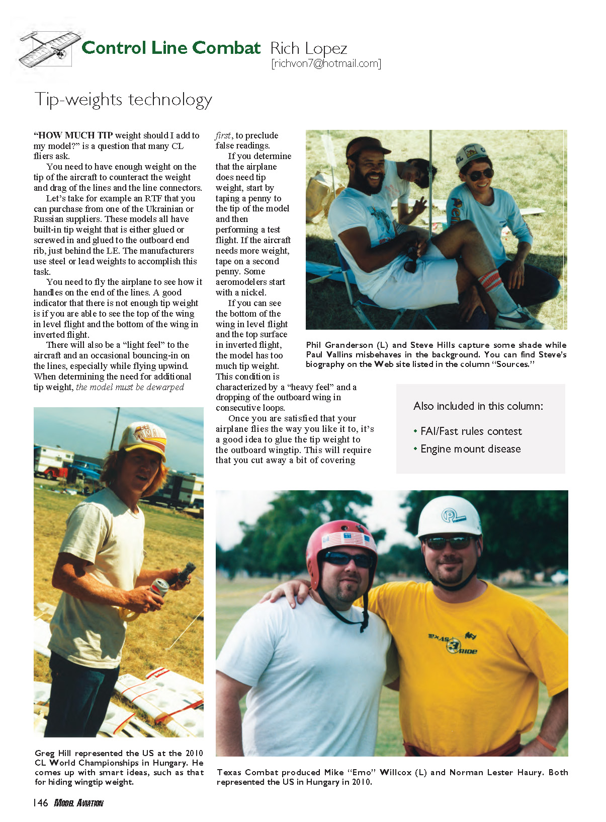
Steve Hills
I mentioned Steve Hills in the September column as having passed away. I found an old photograph of Steve with Phil Granderson in my files that I wanted to share this month.
Sources
- Steve Hills — www.shills.com
- Mike Willcox — [email protected]
- Miniature Aircraft Combat Association — www.maca.hobby-site.com:3535
Transcribed from original scans by AI. Minor OCR errors may remain.

