
CONTROL LINE NAVY CARRIER
Dick Perry 427 Live Oak Ln. NE, Albuquerque, NM 87122 E-mail: [email protected]
CORRECTION
Thanks to all of you who correctly identified Gary Hull’s Douglas TBD Devastator in the January column. I do indeed know the difference between the SBD and the TBD, but the late hour, lack of sleep, and impending deadline took their toll. It’s nice to know that I have so many readers who are paying attention to the details!
NATS
Ted Kraver has offered to serve as event director for the official Carrier events at the Nats. Thanks, Ted. There are plenty of openings for other official and assistant positions. You may volunteer by contacting me or any of the Navy Carrier Society officers.
ENGINE SPEED CONTROL
The means by which we throttle our Carrier models’ engines have seen extensive evolution over the years. I’ve described numerous methods in this column; this month I provide a summary of the history and the interesting throttle options from the past, ending with the method that frequent Navy Carrier Nats winner and record holder Pete Mazur currently uses.
Early methods
The first Navy Carrier events introduced CL modelers to the concept of throttle control. Initial efforts at achieving that control tended to rely on standard bellcranks for elevator and a third line working against a spring for engine speed control.
The actual mechanism for engine speed control started with intake restrictors—usually a flapper valve on the intake of a standard glow engine that put it in a rich setting when closed. Some engines had dual needle valves that did the same thing, adding fuel to reduce engine speed through a rich mixture.
Ignition engines had the option of a separate set of ignition points, which allowed the timing to be changed, reducing the power. Such systems had essentially two speeds—high and low—with the low speed preset on the ground.
Balanced three-line bellcrank and Vari-Speed
J. Robert “Bob” Smurthwaite (J. Roberts) soon introduced the Flight Control balanced three-line bellcrank that we use today. Brodak manufactures today’s system; although it looks slightly different from the J. Roberts units, Bob Smurthwaite developed both designs.
With infinitely variable throttle position a possibility, Bob also introduced the Vari-Speed engine speed control: a slide-type exhaust restrictor which slowed the engine by creating back pressure in the exhaust that limited the fuel that could be introduced to the cylinder when the intake ports were open. It was extremely effective on a suction engine since the reduced airflow through the intake as the engine slowed reduced the fuel flow at the same time.
Pressure fuel systems and Bill Johnson’s solution
As McCoy, Dooling, and other large glow engines became prevalent in Speed circles, they were adapted to Carrier. Pressure fuel systems allowed more open intakes for more power, but throttle schemes such as the Vari-Speed were incompatible with pressure fuel systems because the relatively constant tank pressure and fixed needle-valve setting produced a constant fuel flow, which flooded the engine at low speed.
Bill Johnson developed a solution. He used an exhaust slide coupled with a fuel meter made from brass tubing that restricted the fuel flow as the exhaust slide closed. The open intake maintained a relatively constant tank pressure as engine speed changed.
- The low-speed mixture was controlled by varying the closed position of the slide in relation to the meter, usually via a bendable connecting link.
- The midrange mixture was varied by changing the internal meter geometry, changing the slide geometry, or changing the length of the arm where the connecting link attached to the meter.
It was a reliable system after initial tinkering to produce the optimum settings. Significant changes in fuel or propeller could require a new set of adjustments.
Refinements
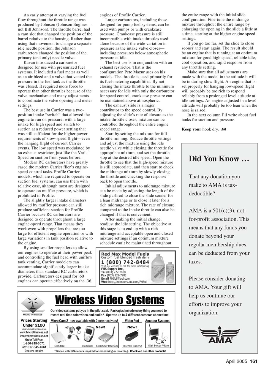
Refinements included a meter by Harry Higley that allowed for internal adjustment of the low-speed mixture. A rotary variant of the exhaust slide was used by some flyers, including the version shown in a photograph on one of Leon Rykartsyk’s models.
Intake throttles and RC carburetors
Intake throttles came to glow engines with radio control. Initial idle mixture adjustment was via an adjustable air bleed that changed the intake pressure for the suction fuel system, thus changing the fuel flow.
An early attempt at varying the fuel flow throughout the throttle range was produced by Johnson (Johnson Engines—not Bill Johnson). The throttle barrel had a cam slot that changed the position of the barrel relative to the housing. Rather than using that movement to change a separate idle needle position, the Johnson carburetors changed the position of the primary (and only) needle valve.
Kavan introduced a carburetor designed for use with pressurized fuel systems. It included a fuel meter as well as an air bleed and a valve that vented the pressure in the fuel tank as the throttle was closed. It required more force to operate than other throttles because of the valve mechanism and required many adjustments to coordinate the valve opening and meter settings.
The best use in Carrier was a two-position intake "switch" that allowed the engine to run on pressure with a large intake for high speed, then switch to suction at a reduced power setting that was still sufficient for the higher power requirements of slow-speed flight—even the hanging flight of current Carrier events. The low speed was modulated by an exhaust restrictor, just like the Vari-Speed on suction from years before.
Modern RC carburetors and Profile Carrier
Modern RC carburetors have greatly eased the modern Carrier flier’s engine-speed-control tasks. Profile Carrier models, which are required to operate on suction fuel systems, can use them with relative ease, although most RC carburetors are designed to operate on muffler pressure, which is prohibited in Profile.
The slightly larger intake diameters allowed by muffler pressure can still produce sufficient suction for Profile Carrier because RC carburetors are designed to operate throughout a large engine-speed range. That means they work even with propellers that are too large for efficient engine operation or with large variations in tank position relative to the engine.
By using smaller propellers to allow our engines to operate at their peak power and controlling the fuel head with uniflow tank venting, Carrier modelers can accommodate significantly larger intake diameters than standard RC carburetors provide. Carburetors designed for .60 engines can operate effectively on the .36 engines of Profile Carrier.
Carburetors with pumps or crankcase pressure
Larger carburetors, including those designed for pump fuel systems, can be used with pumps or with crankcase pressure. Crankcase pressure is still incompatible with intake throttles used alone because of the wide variation in pressure as the intake valve closes—including pressures below atmospheric pressure at idle.
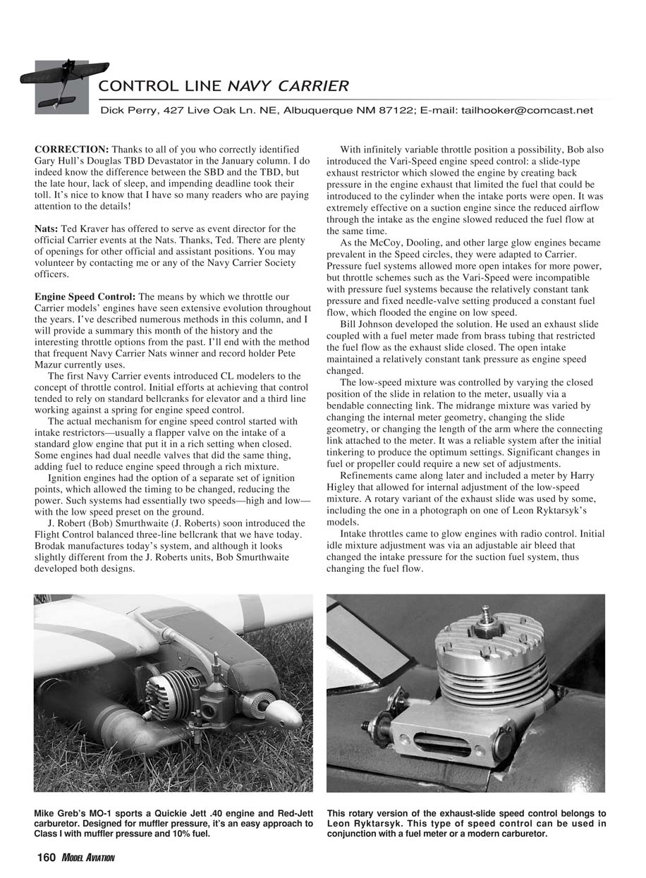
The best use is in conjunction with an exhaust restrictor. That is the configuration Pete Mazur uses on his models. The throttle is used primarily for its fuel-metering capabilities. By not closing the intake throttle to the minimum necessary for idle when using the carburetor for speed control, crankcase pressure can be maintained above atmospheric.
The exhaust slide is a major contributor to speed control. By adjusting the slide’s rate of closure as the intake throttle closes, mixture can be controlled throughout the entire engine speed range.
Setting up the system (procedure)
Start by setting the mixture for full-throttle running. Then:
- Reduce throttle settings and adjust the mixture using the idle needle valve while closing the throttle for appropriate mixture.
- Set the throttle stop at the desired idle speed.
- Open the throttle to verify the high-speed mixture is still appropriate.
- Check the midrange mixture by slowly closing the throttle and observing the response back to open throttle.
Initial adjustments to midrange mixture can be made by adjusting the length of the slide pushrod to close the slide sooner for a lean midrange or to close it later for a rich midrange mixture. The rate of closure compared to the intake throttle can also be changed if convenient.
After making the initial change, readjust the idle setting. The objective at this stage is to end up with a rich midrange and acceptable open- and closed-throttle mixture settings if an optimum mixture schedule can’t be maintained throughout the entire range with the initial slide configuration. Fine-tune the midrange mixture throughout the entire range by enlarging the opening in the slide a little at a time, starting at the higher engine speed settings.
If you go too far, set the slide to close sooner and start again. The result should be an engine that is running at an optimum mixture for good high speed, reliable idle, cool operation, and rapid response from any throttle setting.
Make sure that all adjustments are made with the model in the attitude it will be in during slow flight. An engine that is set properly for hanging low-speed flight will probably be too rich to respond reliably from a prolonged level attitude at idle settings. An engine adjusted in a level attitude will probably be too lean when the nose is raised.
In the next column I’ll write about fuel tanks for suction and pressure.
Keep your hook dry. MA
Transcribed from original scans by AI. Minor OCR errors may remain.

