
Control Line Navy Carrier - 2006/01
Dick Perry [[email protected]]
More about pressure fuel systems for Carrier models
With this issue coming out during the building season for most Navy Carrier modelers, I’m sure there are some new creations taking shape on your building boards that would be of interest to this column’s readers. I encourage you to send me a photo or two of your latest project for inclusion in future editions of this column. The publication standards require a 35mm film print (preferably on glossy paper) or a file on CD from a camera with a minimum of 3 megapixels taken in high-resolution mode. Try to have the model against an uncluttered background and the background relatively close to the model if you are photographing with a flash.
This month I’ll continue the discussion of fuel tanks, which I started in the November column. A problem we face with pressure fuel systems comes from the fact that the engine’s crankcase pressure output varies significantly with engine speed.
If you are using an intake throttle that reduces airflow into the engine at lower engine speeds as the primary means of controlling the engine speed, the average crankcase pressure can be even lower than atmospheric at idle. If the tank end of the pressure line is in contact with fuel as the pressure changes, higher pressure in the tank can force fuel back to the engine through the pressure line when engine speed is reduced. I’ve used a check valve in the pressure line to keep tank pressure more constant, but variations in pressure are too great to allow optimum consistency in that mode of operation. It is an effective means of keeping fuel from flowing back through the pressure line, but the other disadvantages outweighed that single advantage. One could also set up the tank so the tank end of the pressure line is in a part of the tank that is normally not going to result in the end of the line being immersed in fuel. That concept is good, but the realities of turbulence, vibration, acceleration, etc., make it hard to rely on.
In full-scale aircraft, especially larger airplanes in which there can be significant fuel expansion caused by temperature after the tanks are filled, a surge tank is used to catch the fuel that is forced out of the fuel tanks through the vent lines. As fuel is used or as the fuel temperature falls in the colder air at cruise altitudes, the fuel that is captured by the surge tank is returned to the main fuel tanks. We can have the equivalent of the surge tank in our models’ pressure lines.
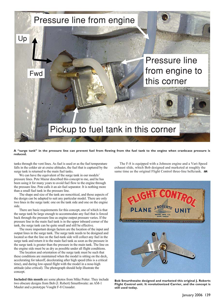
Pete Mazur described this concept to me, and he has been using it for many years to avoid fuel flow to the engine through the pressure line. Pete calls it an air–fuel separator. It is nothing more than a small fuel tank in the pressure line. The shape and size of the tank are noncritical, and those aspects of the design can be adapted to suit any particular model. There are only two lines in the surge tank: one on the tank side and one on the engine side.
Basic requirements for this concept include:
- The surge tank must be large enough to accommodate any fuel that is forced back through the pressure line as engine output pressure varies. If the pressure line in the main fuel tank is in the upper inboard corner of the tank, the surge tank can be quite small and still be effective.
- The location of the input and output lines in the surge tank is important. The surge tank needs to be designed and located so that the line on the fuel-tank side will collect any fuel in the surge tank and return it to the main fuel tank as soon as the pressure in the surge tank is greater than the pressure in the main tank.
- The line on the engine side must be as dry as possible under all flight conditions.
The location and orientation of the surge tank must be such that these conditions are maintained during normal operations, including:
- when the model is sitting on the deck,
- accelerating for takeoff,
- decelerating after high speed (this is a critical time), and
- during low-speed flight with the model in a nose-high attitude (also critical).
The photograph should help illustrate the concept.
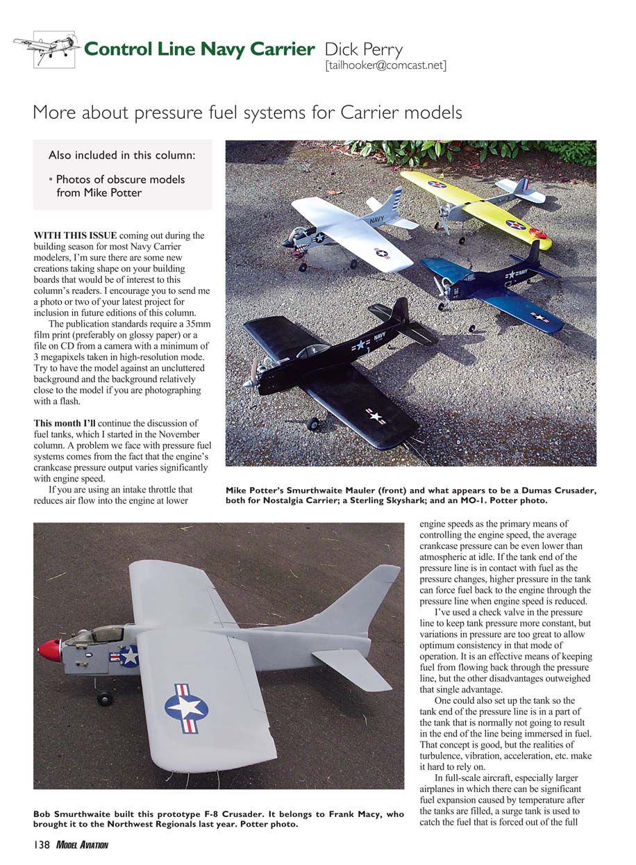
Included this month are some photos from Mike Potter. They include two obscure designs from Bob (J. Robert) Smurthwaite: an AM-1 Mauler and a prototype Vought F-8 Crusader.
Transcribed from original scans by AI. Minor OCR errors may remain.

