
Control Line Navy Carrier — 2007/07
Dick Perry [[email protected]]
Eric Conley’s innovative line "slider"
Also included in this column:
- Balancing issues for low and high speed
- Nats event sponsors
- Electric-powered Carrier
- Answers to the Corsair quiz
As in the April column, the photos this month are of Eric Conley’s Corsair Profile Carrier model. I photographed it at the Southwest Regionals in Tucson, Arizona, in January.
Slider mechanism
There have been many varieties of line sliders, snappers, or other means of moving the leadouts aft to yaw the model outboard during slow flight. I’ve mentioned most of them in this column through the years. Although there are few new ideas in this arena, Eric’s method of varying leadout position has some new techniques.
The basics of any slider mechanism include a guide that controls the position of the leadouts throughout their travel and a means of holding the lines forward for high speed and releasing them for low speed. Most mechanisms, including Eric’s, rely on mounting the bellcrank aft of the model’s balance point to generate the force to move the lines to the rear.
The photographs provide enough detail to allow the mechanism to be reproduced. Dimensions are noncritical.
The line guide and retainer are made from five-ply birch plywood, with the areas that contact the leadouts sanded extremely smooth. Hardening the contact surfaces with cyanoacrylate glue would probably also be a good idea.
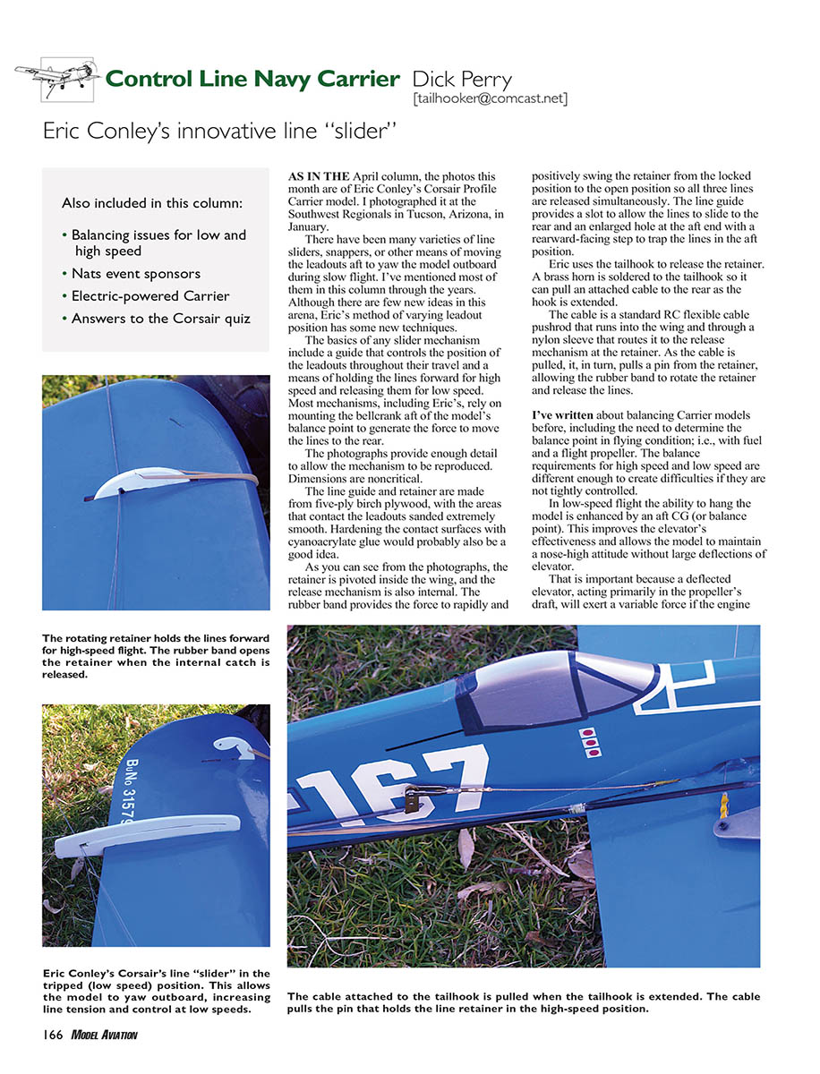
As you can see from the photographs, the retainer is pivoted inside the wing, and the release mechanism is also internal. The rubber band provides the force to rapidly and positively swing the retainer from the locked position to the open position so all three lines are released simultaneously. The line guide provides a slot to allow the lines to slide to the rear and an enlarged hole at the aft end with a rearward-facing step to trap the lines in the aft position.
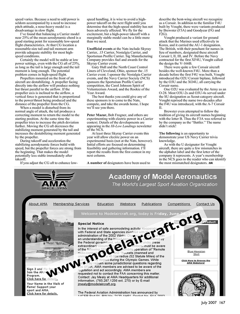
Eric uses the tailhook to release the retainer. A brass horn is soldered to the tailhook so it can pull an attached cable to the rear as the hook is extended.
The cable is a standard RC flexible cable pushrod that runs into the wing and through a nylon sleeve that routes it to the release mechanism at the retainer. As the cable is pulled, it, in turn, pulls a pin from the retainer, allowing the rubber band to rotate the retainer and release the lines.
Balancing Carrier models (low vs. high speed)
I’ve written about balancing Carrier models before, including the need to determine the balance point in flying condition; i.e., with fuel and a flight propeller. The balance requirements for high speed and low speed are different enough to create difficulties if they are not tightly controlled.
In low-speed flight the ability to hang the model is enhanced by an aft CG (or balance point). This improves the elevator’s effectiveness and allows the model to maintain a nose-high attitude without large deflections of elevator. That is important because a deflected elevator, acting primarily in the propeller’s draft, will exert a variable force if the engine speed varies.
Because a need to add power is seldom accompanied by a need to increase pitch attitude, a nose-heavy model is a disadvantage in slow flight.
I’ve found that balancing a Carrier model near 25% of the mean aerodynamic chord is a good starting point for reasonable low-speed flight characteristics. At that CG location a reasonable-size tail and tail moment arm provide adequate stability for most high-speed conditions. Certainly the model will be stable at low power settings, even with the CG aft of 25%, as long as the tail is large enough and the tail moment is long enough. The potential problem comes in high-speed flight.
Propellers mounted on the front of an aircraft are destabilizing. A propeller facing directly into the airflow will produce nothing but thrust parallel to the airflow. If the propeller axis is inclined to the airflow, a vertical force is generated that is proportional to the power/thrust being produced and the distance of the propeller from the CG.
When a model is disturbed from its normal angle of attack, the tail produces a correcting moment to return the model to the starting position. At the same time the propeller tries to increase the pitch deviation further. Moving the CG aft decreases the stabilizing moment generated by the tail and increases the destabilizing moment generated by the propeller.
During takeoff and acceleration the stabilizing aerodynamic forces build with speed, but the propeller forces are strong from the beginning. That makes the model potentially less stable immediately after takeoff.
If you adjust the CG aft to enhance low-speed handling, it is wise to avoid a high-power takeoff on the next flight until you determine that the high-speed stability has not been adversely affected. We fly for the excitement, but a high-power takeoff with a marginally stable model can be a little more than we need.
Nats events and sponsors
Unofficial events at the Nats include:
- Skyray Carrier
- .15 Carrier
- Nostalgia Carrier
- Sportsman Profile Carrier
Sponsors:
- Sig Manufacturing Company provides fuel and awards for the Skyray Carrier event.
- Gary Hull and the North Coast Control Liners of Cleveland, Ohio, sponsor the .15 Carrier event.
- I sponsor the Nostalgia Carrier events.
- The Navy Carrier Society (NCS) sponsors the Sportsman Profile Carrier competition, the Carol Johnson Spirit of Volunteerism Award, and the Rookie of the Year Award.
The best thanks you could give any of these sponsors is to come to the Nats, compete, and take the awards home. I hope we’ll see you there.
Electric-powered Carrier
Peter Mazur, Bob Frogner, and others are experimenting with electric power in a Carrier context. Details of the developments are appearing in the Hi-Low Landings newsletter of the NCS.
At least three Skyray Carrier events this year will allow electric power on an experimental basis (not at the Nats, however). Initial efforts are focused on determining feasibility and gathering information. I'll report the results from the first contest in my next column.
Corsair history and trivia
A number of designators have been used to describe the bent-wing aircraft we recognize as a Corsair. In addition to the familiar F4U built by Vought, there were variants produced by Brewster (F3A) and Goodyear (FG and F2G).
Vought produced a variant for ground attack that the Marines used effectively in Korea, and it carried the AU-1 designation. The British, with their penchant for names in lieu of numbers, designated these aircraft Corsair I, II, III, and IV. Before the Navy contracted for the first XF4U, Vought called the design the V-166B.
There were quite a few Corsair aircraft besides the well-known F4U. More than a decade before the first F4U was built, Vought introduced the O2U Corsair biplane, followed by the O3U and the XO4U, all carrying the Corsair name.
One O2U was evaluated by the Army as an O-28. Most O3U-2s and O3U-4s served under the SU designation as scout-category aircraft. Vought reprised the name two decades after the F4U was introduced, with the A-7 Corsair II.
Brewster even attempted to follow the tradition of giving its aircraft names beginning with the letter B. Thus the F3A was referred to by the company as the "Battler." The name didn't stick.
The following is an opportunity to demonstrate your US Navy Carrier trivia knowledge.
As with the U designator for Vought aircraft, there are quite a few mismatches in the alphabet label and the first letter of the company it represents. A year's membership in the NCS goes to the reader who can identify the most mismatched designators.
MA
Transcribed from original scans by AI. Minor OCR errors may remain.

